LDC401 & LDC401A Automated Cleavers Chapter 7: Cleaving
Page 20 TTN100064-D02
The Micrometer Backstop acts as a backing for the fiber during the Cleave Process. When using the Micrometer
Backstop, it is possible to reduce the tension applied to the fiber because the Micrometer Backstop will prevent the
fiber from flexing when struck by the blade to produce a longer initial scribe. The longer initial scribe causes the
fiber to cleave, despite the relatively low tension. Since the tension is lower, the crack propagates slowly with little
driving force, and a smoother cleave surface results. The Micrometer Backstop may be used in conjunction with the
“Subcritical Process” to produce cleaves with very good end face quality.
A general rule to follow when using the Micrometer Backstop is that the Cleave Tension should initially be lowered
to 85% of the Auto Parameter value that Tablet Controller recommends for the diameter of the part. Adjust the
tension based upon visual inspection of the end face. Increase the tension if there is no end face damage but the
cleave has an angle. Decrease the tension if there is end face damage but no angle. Do not go below 60% of the
Auto Parameter value or severe blade damage may result.
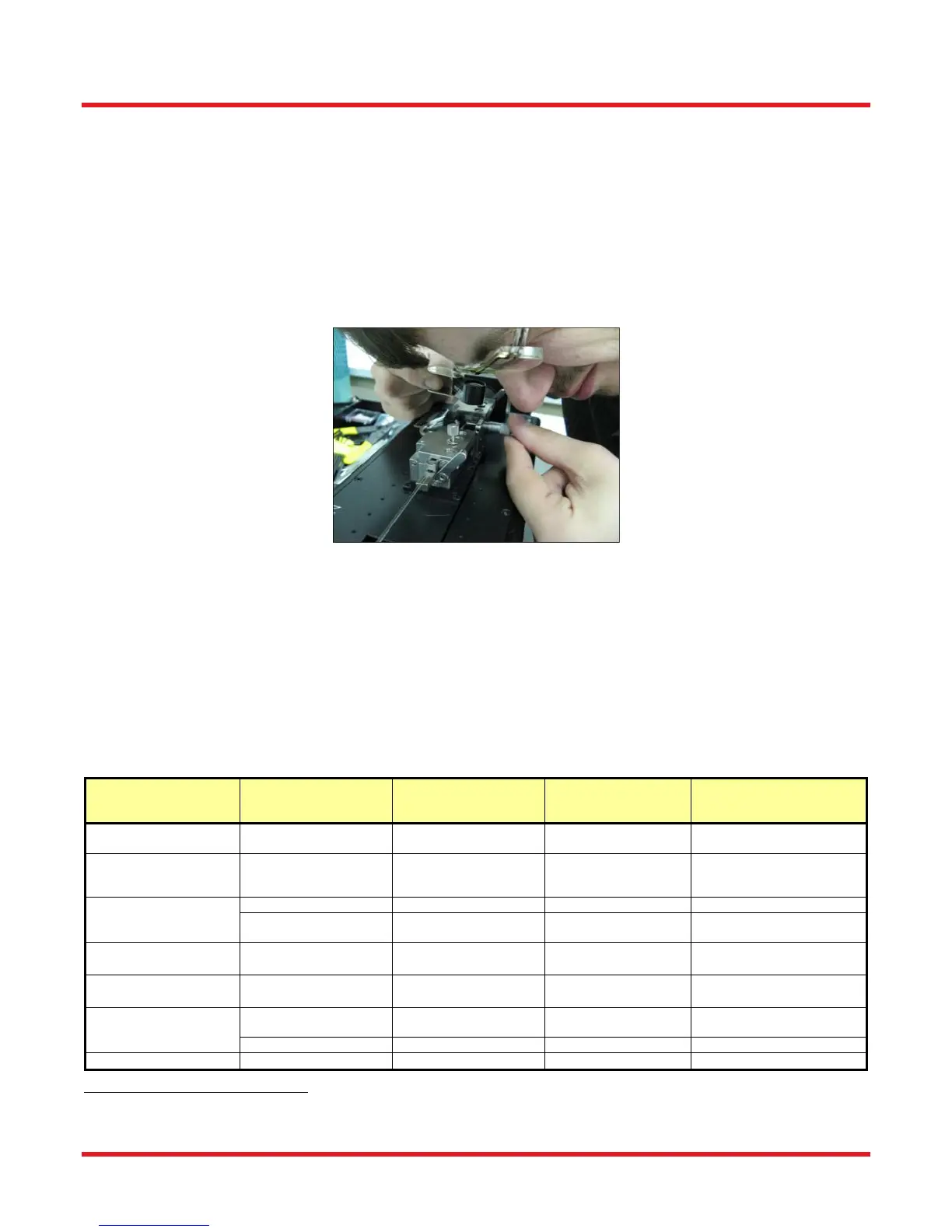
Figure 20 Using an Eye Loupe to Check that the Micrometer Backstop just Touches the Fiber
To use the Micrometer Backstop, load the fiber in to the unit in the normal way, but do not initiate a cleave
immediately. Rotate the micrometer until it just contacts the fiber. It is a good idea to use a 10X eye loupe to make
sure that the Micrometer Backstop just barely touches the fiber (see Figure 20). After the Micrometer Backstop is
set, initiate the cleave as per standard procedure. Be careful not to flex the fiber forwards, or the results will be
poorer than not using the micrometer at all!
After cleaving, back the micrometer away from the cleaved fiber prior to unloading. This will ensure that the fiber
does not contact the micrometer during unloading.
The following chart offers guidelines for when to use the Subcritical Process and the Micrometer Backstop.
Process Selection Chart
Fiber Type
Cleave
Type
Standard
Process
SubCritical
Process
Micrometer
Backstop
Cladding <Ø800 µm
Flat or
Angled
1
- -
Cladding ≥Ø800 µm
Flat or
Angled
1
May be Necessary
Use if the Blade is Pushing
the Fiber Forwards without
Cleaving
Multimode
Flat
- -
Angled
1
-
Use if Fiber Cladding is
>Ø400 µm
Thick-Walled
Capillary Tubing
2
Flat or
Angled
1
- -
Thin-Walled
Capillary Tubing
3
Flat or
Angled
1
-
PM
Flat
Use if Fiber Cladding is
≤Ø400 µm
Use if Fiber Cladding is
>Ø400 µm
Angled -
PCF
Flat or Angled
1
-
1
Only the LDC401A can be used to produce angled cleaves.
2
Wall thickness is at least 10% of the diameter.
3
Wall thickness is less than 10% of the diameter.
 Loading...