Thundercomm EB5 Edge AI Box Hardware User Manual
- 12 -
Table 3-1.Front view light location and specification
1 Power Indicator/Button Instruction of electric indicator light under safety condition:
EB5 supports power-on startup
Press the button in the state of power on and the system will start the
safe power down process.
Long press the button for 10 seconds in the state of power on, and the
system starts to force the power flow down
Under the state of power down, press the button briefly and the system
starts the power up process.
The EB5 implements a dual functionality pushbutton for both Reset and
Power up/Power down of the platform. To power the module, simply press
and hold the pushbutton for a minimum of 250 milliseconds. To put the Edge
box module into Force Reset mode, press and hold the pushbutton for a
minimum of 10 seconds.
Power status indicator:
Green (bright): EB5 is working;
Green:(flashing): EB5 is in the process of the electric;
Green:(put out): EB5 complete operation;
Green (bright): EB5 is working;
Red:(flashing): EB5 connection is broken;
Lights extinguished: WIFI off;
Green (bright): EB5 is working;
Red:(flashing): EB5 connection is broken;
Lights extinguished: 5G off;
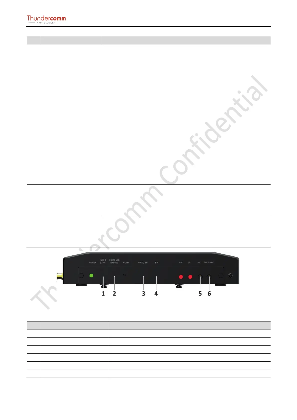
Figure 3-5. Front View Connector Location
Table 3-2.Front view connector location and specification
No. Name Instruction
1 Type-C Behind the baffle, used for ADB debugging.
Behind the baffle, used for UART debugging Port.
Behind the baffle, used for ADB debugging.
Behind the baffle, used for storage extension.
3.5 inch MIC input interface
3.5 inch Earphone output interface