Do you have a question about the Thundercomm Qualcomm Robotics RB5 and is the answer not in the manual?
Overview of the RB5 Development board's key hardware components and specifications.
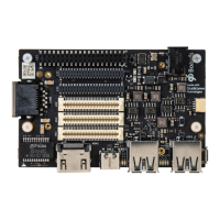
Visual representations and identification of connectors and components on the development board.
Glossary of technical terms and definitions used throughout the hardware user manual.
Lists the necessary hardware components for setting up and operating the development kit.
Step-by-step guide for booting the Ubuntu Embedded OS on the development board.
High-level overview of the system architecture and data flow of the RB5 Development Kit.
Details on the processor, memory configuration, and MicroSD slot.
Information on Wi-Fi/BT, Display Interface, and MIPI-DSI for connectivity and display.
Details on camera interfaces and various USB ports (Host, Type-C).
Description of audio interfaces (BT, DisplayPort) and DC power/battery options.
Information on buttons, LEDs, fan connection, UART, and JTAG.
Overview of expansion connectors and additional implemented functionalities.
Details on inertial sensors and DIP switch configurations for board settings.
Overview of the three high-speed expansion connectors.
Pinout and signal descriptions for the LS1 low-speed expansion connector.
Details on UART, I2C, and GPIO interfaces available on the LS1 connector.
Information on SPI, PCM/I2S, and power/reset button routing for LS1.
Description of the three power rails provided on the LS1 connector.
Pinout and signal descriptions for the LS2 low-speed expansion connector.
Details on audio, microphone, CAN, and I2C interfaces on the LS2 connector.
Description of additional GPIOs and voltage signals available on the LS2 connector.
Pinout and signal descriptions for the LS3 low-speed expansion connector.
Details on SSC SPI, SSC I2C, and sensor interrupt signals for LS3.
Other voltage signals available on the LS3 connector.
Pinout and signal descriptions for the HS1 high-speed expansion connector.
Details on MIPI DSI, MIPI CSI, I2C, HSIC, Reserved, and SD/SPI for HS1.
Information on camera clocks and USB data lines for the HS1 connector.
Pinout and signal descriptions for the HS2 high-speed expansion connector.
Details on MIPI CSI, Clock, SPI, PCIe1, and USB interfaces for HS2.
Additional GPIOs and signals on the HS2 connector.
Pinout and signal descriptions for the HS3 high-speed expansion connector.
Details on MIPI CSI, Clock, PCIe interfaces, MIPI-DSI, and other signals for HS3.
Specifies DC power input methods and guidelines for selecting a single power source.
Describes power activation sequences and methods for measuring power consumption.
Details on measuring DC input current and PMIC power input.
Comprehensive details on the functionality of all onboard buttons (Power, Volume, Reset, USB Boot).
Information about the power, status, and user-programmable LEDs on the RB5 board.
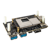
Details about the RB5 Navigation Mezzanine board for connecting cameras.
Technical specifications for the Navigation Mezzanine, including connectors and cameras.
Visual layout and component identification for the Navigation Mezzanine board.
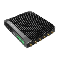
Information on the Machine Communication Mezzanine for cellular network connectivity.
Technical specifications for the Machine Communication Mezzanine.
| GPU | Adreno 650 |
|---|---|
| DSP | Hexagon 698 |
| Memory | 8GB LPDDR5 |
| Storage | 128 GB UFS |
| Processor | Qualcomm® QRB5165 processor |
| CPU | Kryo 585 |
| AI Engine | Qualcomm AI Engine |
| Connectivity | Wi-Fi 6, Bluetooth 5.1 |
| Operating System | Android |