Robotics RB5 Development Kit Hardware User Manual
Copyright© 2020 Thundercomm Technology Co., Ltd. All rights reserved.
10
96Boards specification also calls for a MIPI-DSI interface to be routed to the High Speed
Expansion connector. Since the QRB5165 has two MIPI-DSI interface for HDMI, two
multiplexing devices (FSA644UCX) are used. Only one interface, HDMI, or the Expansion
MIPI-DSI can be active at one time. Control signal,‘DIP_HDMI_SWITCH’, comes from DIP
switch#16. When this signal is set to OFF state, DIP_HDMI_SWITCH is logic HIGH‘1’,
MIPI-DSI signals will be routed to DSI-HDMI Bridge. When the signal of DIP switch is set
to ON state, DIP_HDMI_SWITCH as logic LOW‘0’, MIPI-DSI signals will be routed to the
High Speed Expansion connector.
3.6.2 MIPI-DSI
RB5 has 2x 4-lane MIPI_DSI interface. See below for details.
3.7 Camera Interfaces
RB5 has 6x 4L camera interfaces.
4-lane CSI0 camera on high-speed connector HS1 (section1.2.1 #6) ;
4-lane CSI1camera on high-speed connector HS2 (section1.2. #13)
4-lane CSI2 camera on high-speed connector HS2 (section1.2.1 #13)
4-lane CSI3 camera on high-speed connector HS1 (section1.2.1 #6) and high-speed
connector (section1.2.1 #7)
4-lane CSI4 camera on high-speed connector HS3 (section1.2.1 #7)
4-lane CSI5 camera on high-speed connector HS3 (section1.2.1 #7)
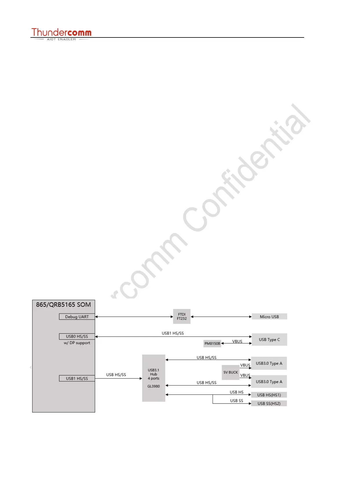
3.8 USB Ports