Robotics RB5 Development Kit Hardware User Manual
Copyright© 2020 Thundercomm Technology Co., Ltd. All rights reserved.
13
Wi-Fi activity LED – RB5 drives this Yellow LED via GPIO_9 from the PMIC (PM8250).
BT activity LED – RB5 drives this Blue LED via GPIO_7 from the PMIC (PM8250).
Four user LEDs
The four user LEDs are surface mount LEDs in 0603 size located next to the two USB Type
A connectors and labeled with ‘USER LEDS 3 2 1 0’.
RB5 drives three of them by the red, green and blue LED drivers from power management
IC PM8150L.
The fourth one is driven by the PM8250 via GPIO_10.
Power indicator LED
A Green LED
3.17 Expansion Connector
The 96Boards specification calls for two expansion connectors, a low-speed connector
and a high-speed connector.
RB5 meets this requirement. See Section 4 for details about the low-speed expansion
connector and Section 5 for high speed expansion connectors.
3.18 Additional Functionality
The 96Boards specification permits additional functionality provided:
All mandatory functionality is available
No impact to the physical footprint specification (including height)
No impact to the use of 96Boards CE low-speed and high-speed expansion facilities
RB5 implements a few additional functions as described from Sections 3.17.1 to 3.17.4
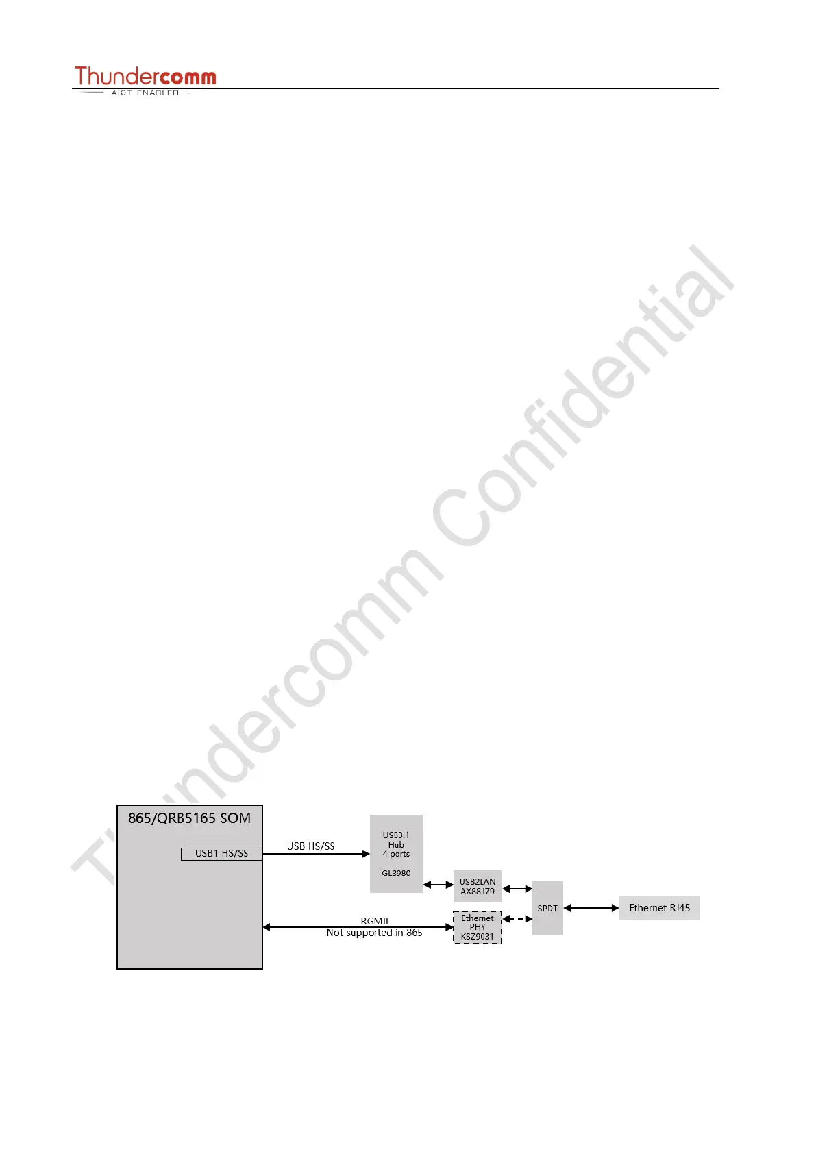
3.18.1 Ethernet Connector
RB5 has the translation from USB1, a USB HUB and a USB to Gigabit Ethernet controller.
RB5 uses an RJ45 (see Section1.2.1, #9) as the physical interface.