Thundercomm EB5 Edge AI Box Hardware User Manual
- 13 -
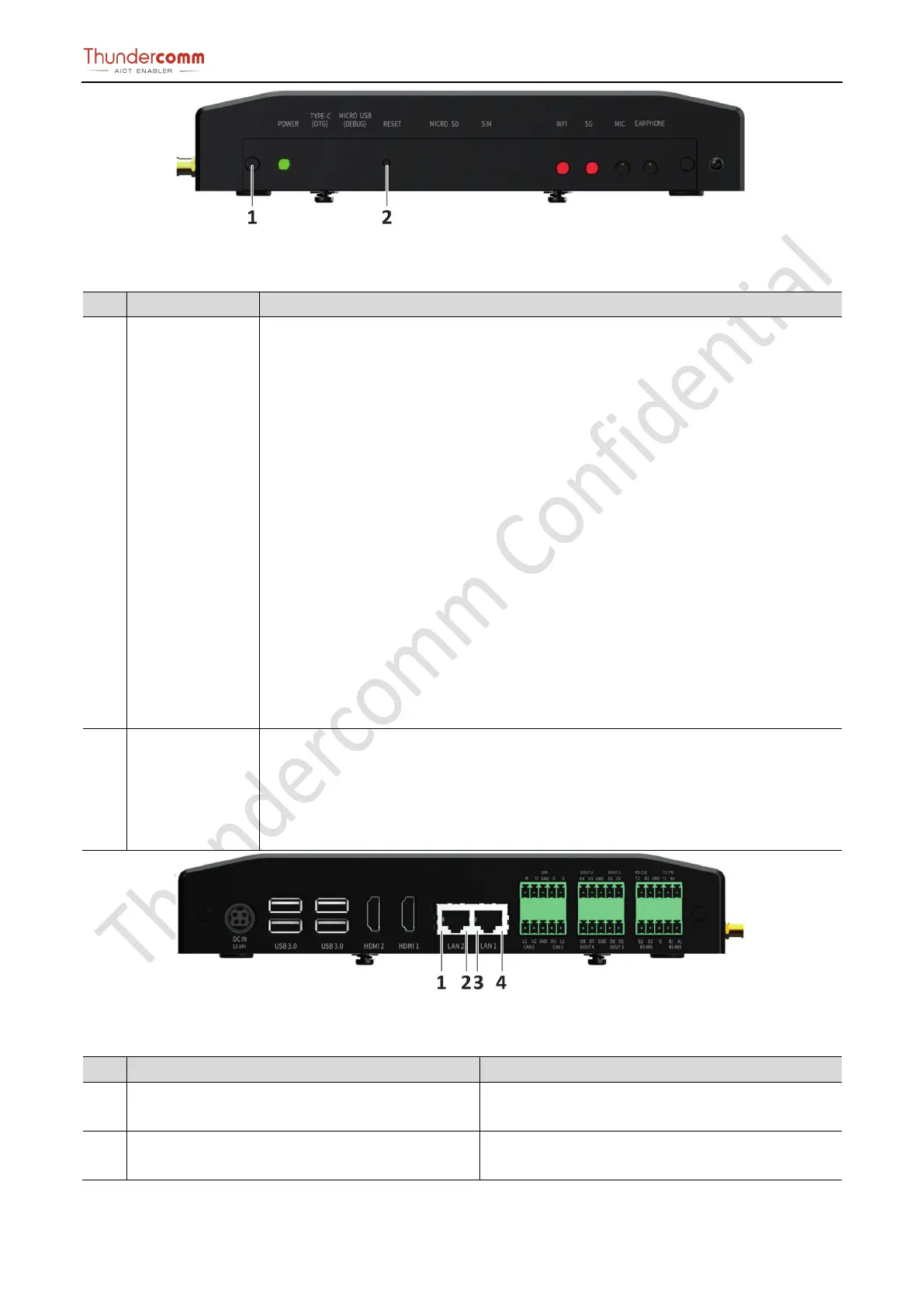
Figure 3-6. Front View Button Location
Table 3-3.Front view button location and specification
1 POWER Button Instruction of electric indicator light under safety condition:
EB5 supports power-on startup
Press the button in the state of power on and the system will start the safe power
down process.
Long press the button for 10 seconds in the state of power on, and the system
starts to force the power flow down
Under the state of power down, press the button briefly and the system starts the
power up process.
The EB5 implements a dual functionality pushbutton for both Reset and Power
up/Power down of the platform. To power the module, simply press and hold the
pushbutton for a minimum of 250 milliseconds. To put the Edge box module into Force
Reset mode, press and hold the pushbutton for a minimum of 10 seconds.
Power status indicator:
Green (bright): EB5 is working;
Green:(flashing): EB5 is in the process of the electric;
Green:(put out): EB5 complete operation;
The EB5 implements a pushbutton for reset
(under development)
Notice:
Restoring factory Settings will cause business interruption, please use this button with
caution.
Figure 3-7. Rear View Ethernet Light Location
Table 3-4.Rear view Ethernet light location and specification
No. Name Instruction
1, 3 Gigabit Ethernet Connector
Light
Lights extinguished: Network not connected
Green (bright):Network connected
2, 4
Gigabit Ethernet Connector Data Transmission
Status Light
Lights extinguished: No data transfer
Yellow:(flashing): Data in transit