Thundercomm EB5 Edge AI Box Hardware User Manual
- 14 -
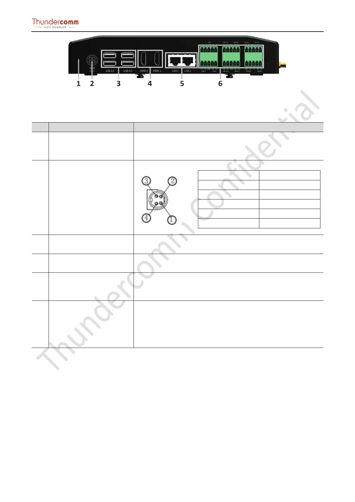
Figure 3-8. Rear View Connector Location
Table 3-5.Rear view connector location and specification
1 GND Use a screwdriver to connect one end of the protective ground wire to
the grounding terminal of the device and the other end to the connection
point of the cabinet or workbench.
2 POWER Connector The Edge box implements a DC JACK+12V to +24V DC power
①
-
②
-
③
+
④
+
Protect -
The EB5 incorporates 4 vertical USB 3.0 Type-A connectors with a 1A
current limit per connector. All USB 3.0 Type-A ports are 5Gbps capable.
4 HDMI Connector
The EB5 module will output video via the Edge box vertical HDMI
connector that is HDMI 1.4 capable.
5 GE Connector The EB5 implements 2 x RJ-
45 ethernet connectors for internet
communication. Connector A and Connector B are connected through a
PCIe Gigabit Ethernet PHY to a PCIe switch.
6 Phoenix Terminal connector If the user uses smoke detector, infrared detector, access control, alarm
and other alarm output equipment.
Connect the cable terminal to the EB5 Phoenix terminal interface and
ensure that both the alarm input device and the EB5 are connected to