35
vd12-14-de-171016
3.3 Transducer Connection RS485
The instrument must be switched off before any transducers are
connected. The use of original accessory cables is recommended.
Disregarding this instruction may lead to damage of the instru-
ment.
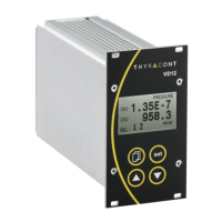
To the RS485 port of the VD12 or VD14 up to two or respectively up to four Thy-
racont Smartline transducers with digital signal output can be connected. The
device provides voltage supply for the transducers.
,3:
-9:
-15:
15pin, male, bolted-type
do not connect
n.c.
-
Transducers connected to the RS485 interface can be arbitrarily assigned to
channel 1 and 2 (VD12) or 1 to 4 (VD14). For this purpose the transducers are
equipped with an address-switch.
If analog transducer ports are used with the VD12, the fixed channel numbers
assigned to those analog ports cannot be applied as an address for digital trans-
ducers (see chapter 3.4).