INSTALLATION
145
NA30 - Manual - 04 - 2022
• 2 m for MRI module (max one module)
• 20 m for MMOS-4 module (max one MMI module)
• 30 m for MID16 and MPT modules
• 2 m for MPT module (max one Pt100 module)
• 2 m for MCI module (max one current converter module)
For upgrading, that may be operated at any time with in service devices too, the following operations
must be performed:
• Turn OFF power supply
• Connect the auxiliary modules to the Thybus port in daisy chain mode following the INPUT-OUTPUT
sequence.
[1]
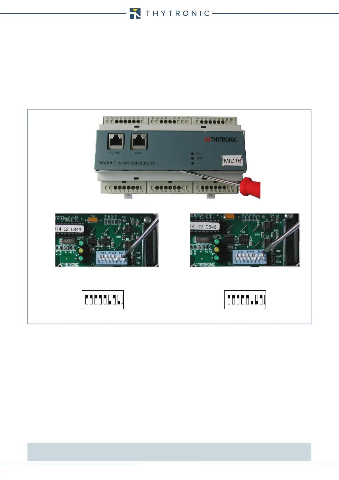
If two MID16 (binary inputs) are installed, the hardware address must be set to avoid communication
collisions on the Thybus; for this purpose the default address must be changed on one module, by
means of dip-switch on the top circuit board (front plate must be removed).
• Turn on power
• Go on to the sw setting (see SETTING section of instruction manual).
Block circuits
Note 1 The insertion order is free.
One MRI module, two MID16 modules, one MPT module, one MCI module and one MMI module (separate operator panel) can be connect at the
same time to the Thybus port (maximum expansion).
S1
1
8
OFF
ON
S1
1
8
OFF
ON
default address
modified address (2nd MID16 module)
DIP-MID16.ai
MID16 hardware address setting
 Loading...


