APPENDIX
189
NA30 - Manual - 04 - 2022
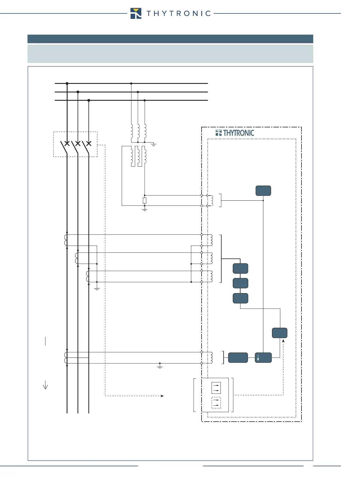
8.6 APPENDIX B3- Connection diagrams
Note: Some typical connection diagram are shown.
All diagram must be considered just as example; they cannot be comprehensive for real applications.
For all diagrams the output contacts are shown in de-energized state for standard reference.
Raf (*)
da
dn
N
A
U
E
(**) Operation for 67N elements for insulated neutral systems and characteristic angle setting = 90°
NA30-SCH.ai
BUSBAR
LINE
Three phase CTs and residual current from core balanced CT
OPERATION (**)
NA30
L1
L2
L3
B7
B8
C1
C2
C3
C4
C5
C6
P1
S1
S2
P2
I
L1
I
L2
I
L3
I
E
C7
C8
P1
S1
S2
P2
* Raf - antiferrorisonance resistor
59N
50N/51N
49
50/51
74CT
67N
BINARY INPUTS
50BF
CB position