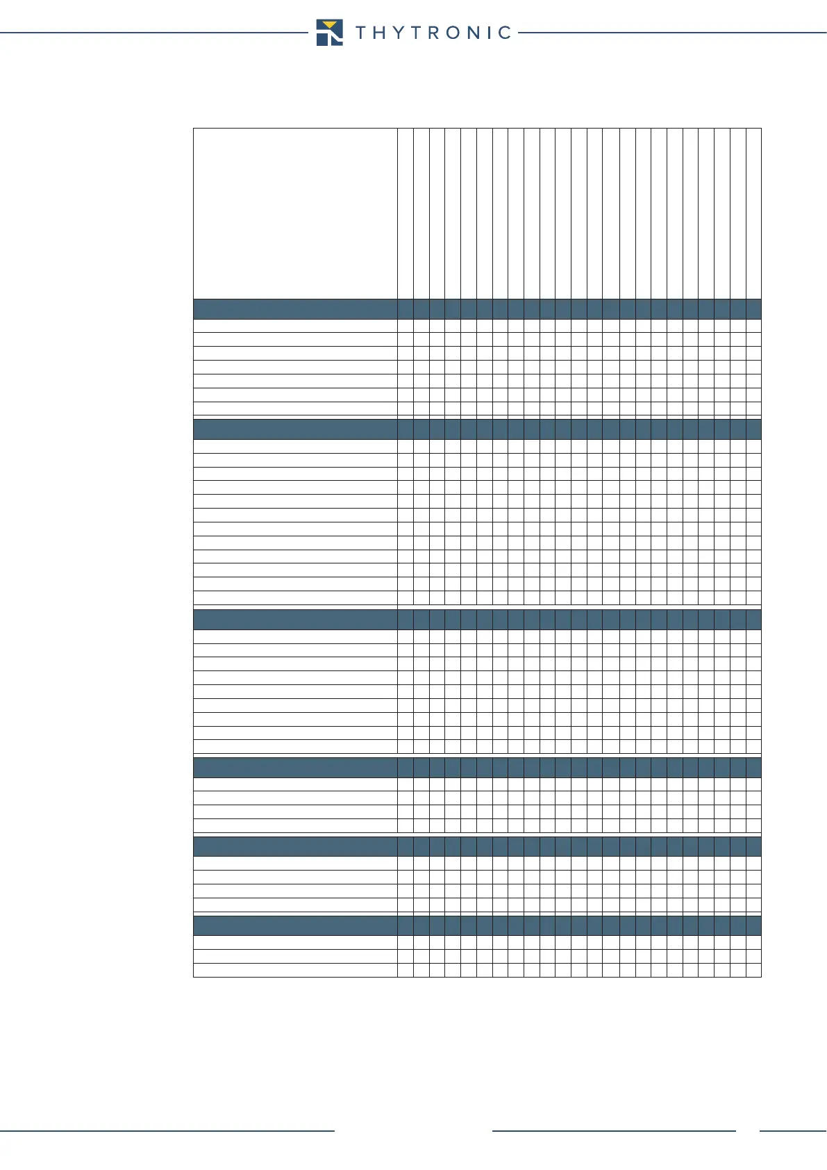
FUNCTION CHARACTERISTICS
34
NA30 - Manual - 04 - 2022
Use of measured values
Usage of measured values for protection, control and monitoring
f
i
L1,
i
L2
, i
L3
I
L1,
I
L2
, I
L3
I
L1-2nd,
I
L2-2nd,
I
L3-2nd
i
E
I
E
I
1
I
2
u
E
U
E
Temperature (PT1....PT8)
Binary input I
Nx
START Relay K1...K6
TRIP) Relay K1...K6
START LEDs L1...L5
TRIP LEDs L1...L5
Selective block input BLIN1
Selective block output BLOUT1
Cold Load Pickup (CLP)
Seconda harmonic restraint
Logic block (Block1)
Logic selectivity (Block2)
Internal logic selectivity (Block4)
PROTECTIONS
Thermometric probes - 26
Thermal image - 49
Phase overcurrent - 50/51
Residual overcurrent - 50N/51N
Residual overvoltage - 59N
Directional earth fault overcurrent - 67N
Breaker failure - BF
CONTROL & MONITORING
CT Monitoring (74CT)
Trip Circuit Supervision TCS)
Second harminic restraint - 2NDH-REST
Logic block (Block1)
Selective block (Block2)
Internal Selective block (Block4)
Self-test
Functions state
Counters
Inputs state
Selective block state
Outputs state
MEASURES
Frequency
Phase currents
Residual current
Inverse sequence current
Direct sequence current
Thermal image
Residual voltage
UE - IE Displacement
Temperature (Pt100 with MPT module)
EVENT RECORDER
Event 0
Event 1
Event ...
Event 299
FAULT RECORDER
Fault 0
Fault 1
Fault ...
Fault 19
OSCILLOGRAPY
Record 1
Record 2
Record ...