FUNCTION CHARACTERISTICS
84
NA30 - Manual - 04 - 2022
Ground directional overcurrent - 67N
Preface
Four operation thresholds, independently adjustable (I
ED
>, I
ED
>>, I
ED
>>> ,I
ED
>>>>) with adjustable delay
(t
ED
>, t
ED
>>, t
ED
>>>, t
ED
>>>>).
Each element can be enabled or disabled.
The first two may be programmed with definite or inverse time according the IEC and ANSI/IEEE
standard, as well as with rectifier, EM curve.
The third and fourth thresholds with independent time.
Moreover several predefined blocking criteria are implemented (threshold trip may be inhibited by
start of the other thresholds, logic selectivity with internal and/or external elements, etc.).
Operation and settings
The first and second threshold (I
ED
>, I
ED
>>) may be programmed with definite or inverse time ac-
cording the following characteristic curves:
• Standard Inverse Time (IEC 255-3/BS142 type A or SIT): t = 0.14 · t
ED
>
inv
/ [(I
ED
/I
ED
>
inv
)
0.02
- 1]
• Very Inverse Time (IEC 255-3/BS142 type B or VIT): t = 13.5 · t
ED
>
inv
/ [(I
PD
/I
ED
>
inv
) - 1]
• Extremely Inverse Time (IEC 255-3/BS142 type C or EIT): t = 80 · t
PD
>
inv
/ [(I
ED
/I
ED
>
inv
)
2
- 1]
• Moderately Inverse (ANSI/IEEE type MI): t = t
ED
>
inv
· {0.01 / [(I
ED
/I
ED
>
inv
)
0.02
- 1] + 0.023}
• Very Inverse (ANSI/IEEE type VI): t = t
ED
>
inv
· {3.922 / [(I
ED
/I
ED
>
inv
)
2
- 1] + 0.098}
• Extremely Inverse (ANSI/IEEE type EI): t = t
ED
>
inv
· {5.64 / [(I
ED
/I
ED
>
inv
)
2
- 1] + 0.024}
• Electromechanical (EM): t = t
ED
>
inv
· {0.28 / [-0236 · (I
ED
/I
ED
>
inv
)
-1
+ 0.339]}
Where:
t: operate time
I
ED
>
inv
: first and second threshold setting (I
ED>inv,
I
ED>>inv
)
t
ED
>
inv
: first and second threshold operate time setting (t
PD>inv,
t
PD>>inv
)
Third and fourth threshold (I
ED>>>def,
I
ED>>>>def
) with definite time.
For all inverse time characteristics, following data applies:
• Asymptotic reference value (minimum pickup value): 1.1 I
ED
> or I
ED
>>
• Minimum operate time: 0.1 s
• Range where the equation is valid:
[1]
1.1 ≤ I
ED
/I
ED
>
inv
(or I
ED
>>
inv
) ≤ 20
• If I
ED
>
inv
(or I
ED
>>
inv
) pickup ≥ 0.5 I
En
, the upper limit is 10 I
En
For all definite time elements the upper limit for measuring is 50 I
n
.
Two different criteria may be selected:
• Residual current threshold overcoming (module)
• Projection residual current threshold overcoming (projection)
The operating mode may be selected by setting the Mode67N parameter, located inside the Set \
Profile A(or B) \ Directional earth fault overcurrent-67N \ Common configuration menu.
The settable operating mode is I (module) or I*cos (projection).
Note 1 When the input value is more than 20 times the set point , the operate time is limited to the value corresponding to 20 times the set point
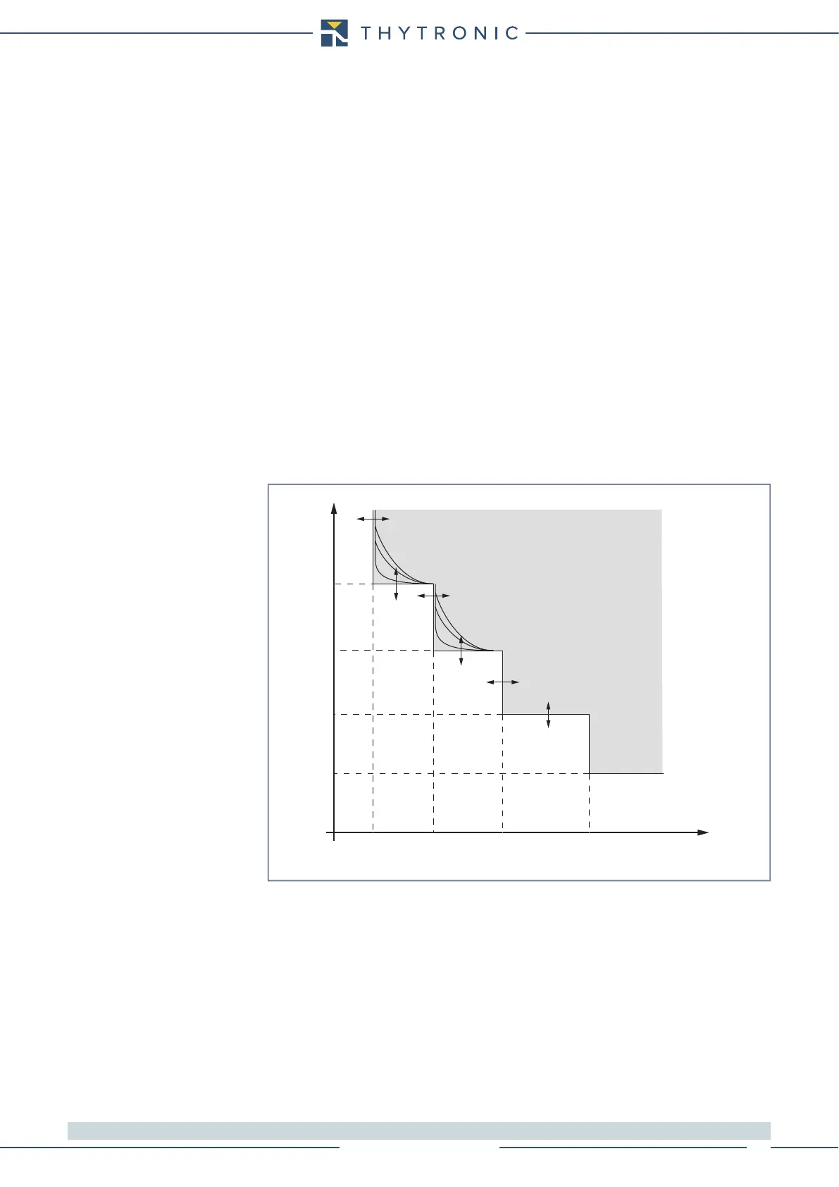
t-int-F67N.ai
I
ED
I
ED
>> I
ED
>>> I
ED
>>>>
t
ED
>
t
ED
>>
t
ED
>>>
t
ED
>>>>
I
ED
>
t
TRIP
General operation time characteristic for the ground directional overcurrent elements - 67N