FUNCTION CHARACTERISTICS
70
NA30 - Manual - 04 - 2022
Residual overcurrent - 50N/51N
Preface
Three operation thresholds, independently adjustable (I
E
>, I
E
>>, I
E
>>>) with adjustable delay (t
E
>,
t
E
>>, t
E
>>>).
The first one (I
E
>) may be programmed with definite or inverse time according the IEC and ANSI/IEEE
standard, as well as with EM curve.
The second and third thresholds (I
E
>>, I
E
>>>) with independent time.
For each threshold a reset time can be set (t
E>RES
, t
E>>RES
, t
E>>>RES
) useful to reduce the clearing
time for intermittent faults.
The first threshold trip may be inhibited by start of the second and/or third threshold (I
E
>>, I
E
>>>).
Similarly the second threshold trip may be inhibited by start of the third threshold (I
E
>>>).
Operation and settings
The residual fundamental frequency current is compared with the setting value. Current above the
associated pickup value is detected and a start is issued. After expiry of the associated operate time
a trip command is issued; if instead the current drops below the threshold, the element is restored.
The first threshold (I
E
>) may be programmed with definite or inverse time according the following
characteristic curves:
• Standard Inverse Time (IEC 255-3/BS142 type A or SIT): t = 0.14 · t
E
>
inv
/ [(I
E
/I
E
>
inv
)
0.02
- 1]
• Very Inverse Time (IEC 255-3/BS142 type B or VIT): t = 13.5 · t
E
>
inv
/ [(I
E
/I
E
>
inv
) - 1]
• Extremely Inverse Time (IEC 255-3/BS142 type C or EIT): t = 80 · t
E
>
inv
/ [(I
E
/I
E
>
inv
)
2
- 1]
• Moderately Inverse (ANSI/IEEE type MI): t = t
E
>
inv
· {0.01 / [(I
E
/I
E
>
inv
)
0.02
- 1] +
0.023}
• Very Inverse (ANSI/IEEE type VI): t = t
E
>
inv
· {3.922 / [(I
E
/I
E
>
inv
)
2
- 1] + 0.098}
• Extremely Inverse (ANSI/IEEE type EI): t = t
E
>
inv
· {5.64 / [(I
E
/I
E
>
inv
)
2
- 1] + 0.024}
• Electromechanical (EM):
t = t
E
>
inv
· {0.28 / [-0236 · (I
E
/I
E
>
inv
)
-1
+ 0.339]}
Where:
t: operate time
I
E
>: pickup value
t
E
>
inv
: operate time setting
For all inverse time characteristics, following data applies:
• Asymptotic reference value (minimum pickup value): 1.1 I
E
>
• Minimum operate time: 0.1 s
• Range where the equation is valid:
[1]
1.1 ≤ I
E
/I
E
>
inv
≤ 20
• If I
E
>
inv
pickup ≥ 2.5 I
En
, the upper limit is 10 I
En
For all definite time elements the upper limit for measuring is 10 I
En
.
All residual overcurrent elements can be enabled or disabled by setting ON or OFF the IE> En-
able, IE>> Enable and/or IE>>> Enable parameters inside the Set \ Profile A(or B)\ Residual
overcurrent-50N/51N \ IE> Element (IE>> Element, IE>>> Element) \ Setpoints menus.
The first overcurrent element can be programmed with definite or inverse time characteristic by
setting the IE>Curve parameter (DEFINITE, IEC/BS A, IEC/BS B, IEC/BS C, ANSI/IEE MI,
ANSI/IEE VI, ANSI/IEE EI, EM) available inside the Set \ Profile A(or B) \ Residual overcurrent-
50N/51N \ IE> Element \ Setpoints menu.
Note 1 When the input value is more than 20 times the set point , the operate time is limited to the value corresponding to 20 times the set point
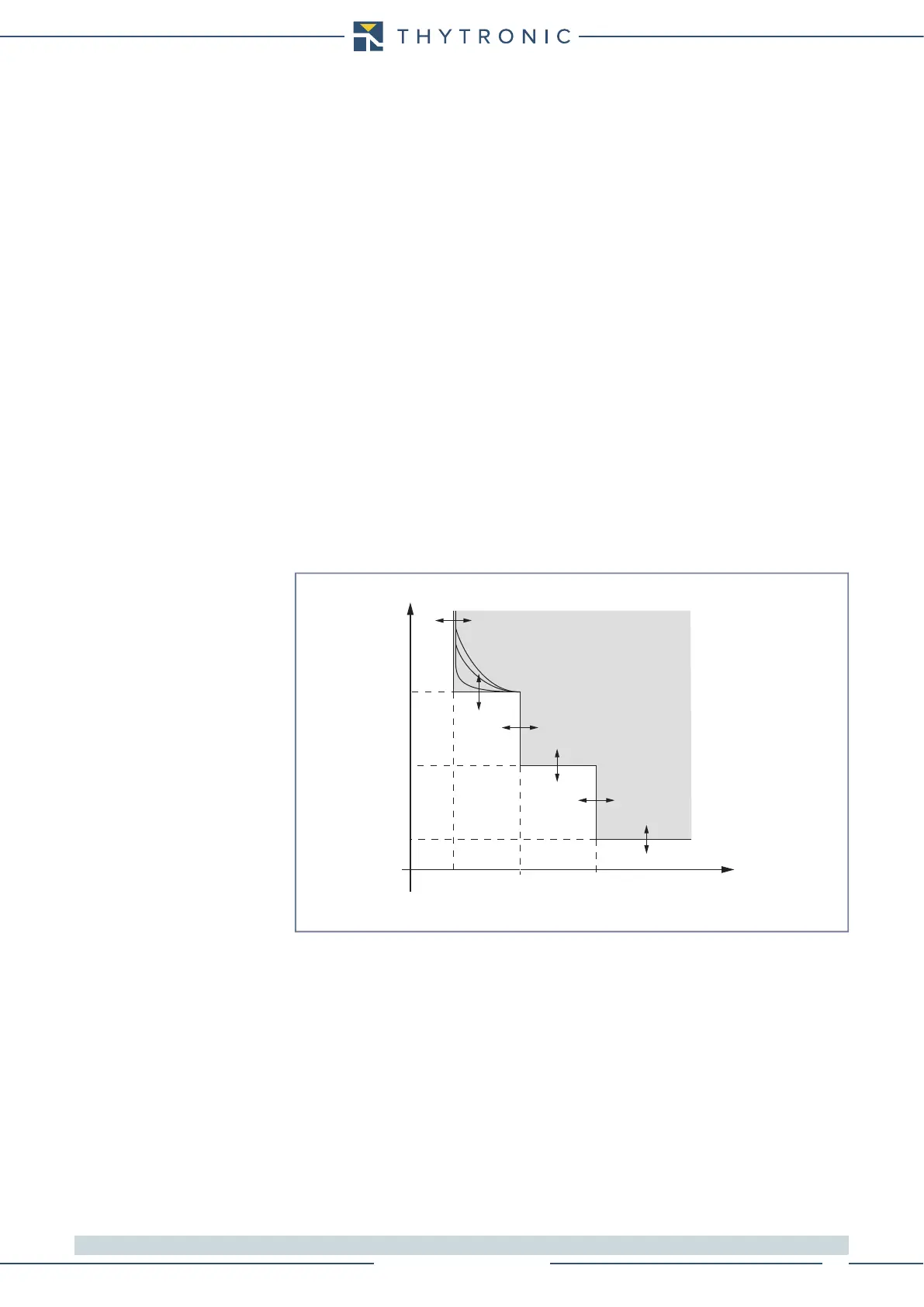
t-int-F50N-51N.ai
I
E
I
E
>> I
E
>>>
t
E
>
t
E
>>
t
E
>>>
I
E
>
t
TRIP
General operation time characteristic for the residual overcurrent elements - 50N/51N