FUNCTION CHARACTERISTICS
48
NA30 - Manual - 04 - 2022
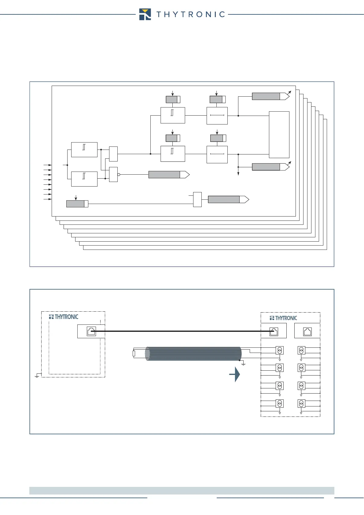
All alarm and/or trip elements can be enabled or disabled by setting ON or OFF the ThALx Enable
e Th>x Enable parameters inside the Set \ Profile A(or B) \ Thermal protection with RTD thermo-
metric probes - 26 \ PTx Probe \ ThALx Alarm (ThALx Trip) where x = 1...8.
Each trip threshold (Th>x) may be associated with the breaker failure (BF) function by setting ON
the Th>xBF parameters inside the Set \ Profile A(or B) \ Thermal protection with RTD thermometric
probes - 26 \ PTx Probe \ ThALx Trip where x = 1...8.
[1]
Note 1 The common settings concerning the Breaker failure protection are adjustable inside the Breaker Failure - BF menu.
Fun-F26.ai
Logic diagram for thermal protection with RTD thermometric probes (26)
T° ≤ +245.0°C
T° > Pt
x
>
Pt
x
Pt1
Pt2
Pt3
Pt4
Pt5
Pt6
Pt7
Pt8
0T
TRIPPING MATRIX
(LED+RELAYS)
T° > Th
ALx
Pt100-x
Trip
Pt100-x
Alarm
t
Th
>
x
t
ThALx
BF Enable (ON≡Enable)
Pt100 OK
Pt100 FAULT
Th>xBF
TOWARDS BF LOGIC
Th>x BF_OUT
TOWARDS DIAGNOSTIC
Pt
x
>
Diagnostic
TRIP
&
&
&
T° ≥ -49.0°C
0T
ThALx-K
ThALx-L
Th>x-K
Th>x-L
Th
ALx
Th
>
x
t
ThALx
t
Th
>
x
Pro_N
E1
THYBUS
PUTNI SUBYHT TUPTUO SUBYHT
MPT
8
T1
PT1 PT8
MPT1 MPT8
PT7
MPT7
PT6
MPT6
PT5
MPT5
PT2
MPT2
PT3
MPT3
PT4
MPT4
T8
7
6
T7
T6
T5
11
T2
12
13
15
T3
16
17
20
T4
21
22
49
48
47
44
43
42
40
39
38
35
34
33
Pt100 probes (Pt1...Pt8)