FUNCTION CHARACTERISTICS
50
NA30 - Manual - 04 - 2022
If the CLP function (Cold Load Pick-up) is enabled for blocking 49, the thermal image is blocked for an
adjustable time interval, starting from the circuit breaker closure.
[1]
The operating mode parameter
may be select by setting ON-Element blocking the DThCLP Mode parameter inside the Set\Pro-
file A(or B)\Thermal image-49\ Common configuration menu.
If the CLP function (Cold Load Pick-up) is enabled for threshold change, the equivalent ther-
mal current may be decreased by means a K
INR
factor for an adjustable time interval, starting
from the circuit breaker closure.
[2]
The operating mode parameter may be select by setting ON-
Change setting the DThCLP Mode parameter inside the Set\Profile A(or B)\Thermal image-49\
Common configuration menu.
For the Dth> threshold, a block from the second harmonic restraint may be set by set-
ting ON the DTh>2ndh-REST parameter inside the Set\Profile A(or B)\Thermal image-49\
Common configuration menu.
All elements can be enabled or disabled by setting ON or OFF the DThetaAL1 Enable, DTheta-
AL2 Enable and/or DTheta> Enable parameters inside the Set\Profile A(or B)\Thermal image-49\
DthAL1 Element (DthAL2 Element, Dth> Element) menus.
The trip element (Dth>) may be inhibited when a start of at least one of the overcurrent element
(50/51) is active, if the Dth>disby50-51 parameter is set ON inside the Set\Profile A(or B)\Thermal
image-49\ Dth> Element menu.
The Dθ
IN
parameter sets a minimum level of previous thermal image Dθ
p
when the protection relay
is powered or when a remote (binary input) or local (keyboard or ThyVisor) command is issued.
The DthIN parameter may be adjusted inside the Set \ Profile A(or B) \ Thermal image-49\
Common configuration menu.
To active the Dθ
IN
preset value remotely, a binary input must be programmed as Init DTheta func-
tion inside the Set \ Inputs \ Binary input IN1, Binary input IN2 menu.
The trip element can produce the Breaker Failure output if the Dth> BF parameters is set to ON.
The parameter is available inside the Set\Profile A(or B)\Thermal image-49 \ Dth> Element menu.
[3]
The IB setting is adjustable inside the Set\Profile A(or B)\Base current IB menu.
Note 1 The CLP function (Cold Load Pick-up) with blocking of the 49 element has priority compared with the second harmonic restraint function, so, if
the equivalent thermal current is enabled, the latter is not reduced when a second harmonic restraint is active.
Note 2 The CLP function (Cold Load Pick-up) with threshold change of the 49 element has priority compared with the second harmonic restraint func-
tion, so, if the equivalent thermal current is enabled, the latter is not reduced when a second harmonic restraint is active.
Note 3 The common settings concerning the Breaker failure protection are adjustable inside the Breaker Failure - BF menu.
all-F49.ai
K
INR
T DthIN DthCLP Mode Dth2ndh REST tDthCLP
Common configuration
I
th
Dth> Element
Trip DTh>
DTh> Enable
DTh>
Trip DTh>
Dth>BF
&
Dth>BF
BLK4OUT
Dth>BLK4
Start I>
&
BLK2OUT
Dth>BLK2OUT
&
Trip Dth>
Trip Dth>
BLK2INDth>
Block2
&
Dth
>BLK2IN
&
DthAL1 Element
DThAL1
DThAL1
DThAL1
DThAL1 Enable
I
th
BLK4OUT
DthAL1BLK4
&
BLK2OUT
DthAL1BLK2OUT
&
Trip Dth>
Block1
BLK1DthAL1
&
DthAL1BLK1
&
Dth>AL1
DthAL1
BLK2INDthAL1
Block2
&
Dth
AL1BLK2IN
&
DthAL2
BLK2INDthAL2
Block2
&
Dth
AL2BLK2IN
&
DthAL2 Element
DThAL2
DThAL2
DThAL2 Enable
I
th
BLK4OUT
DthAL2BLK4
&
BLK2OUT
DthAL2BLK2OUT
&
Block1
BLK1DthAL2
&
DthAL2BLK1
&
Dth>AL2
Dth>AL2
Dth>AL2
Block1
BLK1Dth>
&
Dth>BLK1
Trip Dth>
&
&
50-51 inhibition
Dth>disby50-51
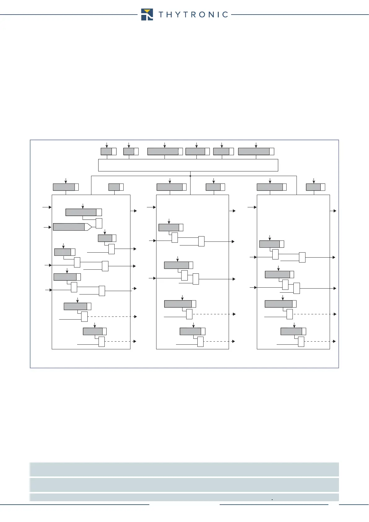
General logic diagram of the thermal image elements - 49