FUNCTION CHARACTERISTICS
88
NA30 - Manual - 04 - 2022
All directional earth fault overcurrent elements can be enabled or disabled by setting ON or OFF the
IED> Enable, IED>> Enable, , IED>>> Enable e/o IED>>>> Enable parameters inside
the Set \ Profile A(or B) \ Directional earth fault overcurrent-67N \ IED> Element (IED>> Element,
IED>>> Element, IED>>> Element) \ Setpoints menus.
The first and second overcurrent element can be programmed with definite or inverse time charac-
teristic by setting theIED>Curve and/or IED>>Curve (DEFINITE, IEC/BS A, IEC/BS B, IEC/
BS C, ANSI/IEE MI, ANSI/IEE VI, ANSI/IEE EI, EM) available inside the Set \ Profile A(or B) \
Directional earth fault overcurrent-67N \ IED> Element (IED>> Element) \ Setpoints menus.
The trip of IED> element may be inhibited by the start of the second, third and/or fourth element (I
ED>>
,
I
ED>>>
, I
ED>>>>
) by setting ON the Disable IED> by start IED>>, Disable IED> by start IED>>>, Dis-
able IED> by start IED>>>> (IED>disbyIED>>, IED>disbyIED>>>, IED>disbyIED>>>>)
parameters available inside the Set \ Profile A(or B) \ Directional earth fault overcurrent-67N
\ IED>> Element (IED>>> Element, IED>>>> Element) \ Setpoints menus.
Similarly the trip of the:
• IED>> element may be inhibited by start of the third and/or fourth element (IED>>> and/or IED>>>>)
by setting ON the Disable IED>> by start IED>>>, start IED>>>> (IED>>disbyIED>>>,
IED>>disbyIED>>>>) parameter available inside the Set \ Profile A(or B) \ Directional earth
fault overcurrent-67N \ IED>>> Element (IED>>>> Element) \S etpoints menus.
• IED>>> element may be inhibited by start of the fourth element (IED>>>>) by setting ON the Dis-
able IED>>> by start IED>>>> (IED>>>disbyIED>>>>) parameter available inside the Set \
Profile A(or B) \ Directional earth fault overcurrent-67N \ IED>>>> Element \ Setpoints menu.
All the named parameters can be set separately for Profile A and Profile B.
An adjustable reset time delay is provided for every threshold (t
ED>RES
, t
ED>>RES
, t
ED>>>RES
, t
ED>>>RES
).
Each directional earth fault element can produce the Breaker Failure output if the IED> BF, IED>>
BF, IED>>> BF and/or IED>>>> BF parameters are set to ON. The parameters are available
inside the Set \ Profile A(or B) \ Directional earth fault overcurrent-67N \ IED> Element (IED>> Ele-
ment, IED>>> Element, IED>>> Element) \ Setpoints menus.
[1]
If the CLP function (Cold Load Pick-up) is enabled for element blocking, the selected threshold may
be blocked for an adjustable time interval, starting from the circuit breaker closure.
This operating mode may be select by setting ON-Element blocking the IEDCLP> Mode, IED-
CLP>> Mode, IEDCLP>>> Mode, IEDCLP>>>> Mode parameters.
If the CLP function (Cold Load Pick-up) is enabled for threshold change, the selected threshold may
be changed for an adjustable time interval, starting from the circuit breaker closure.
This operating mode (ON-Change setting = IEDCLP> Mode, IEDCLP>> Mode, IED-
CLP>>> Mode, IEDCLP>>>> Mode) and the concerning operating time within the CLP (tED-
CLP>, tEDCLP>>, tEDCLP>>>, tEDCLP>>>>) may be adjusted inside the Set \ Profile
A(or B) \ Directional earth fault overcurrent-67N \ IED> Element (IED>> Element, IED>>> Element,
IED>>> Element) \ Setpoints menus, whereas the operating thresholds within the CLP ( IEDCLP>def,
IEDCLP>inv,....) may be adjusted inside the Set \ Profile A(or B) \ Directional earth fault overcur-
rent-67N \ IED> Element (IED>> Element, IED>>> Element, IED>>> Element) \ Definite time (Inverse
time) menus.
For every of the four thresholds the following block criteria are available:
Logical block (Block1)
If the IED>BLK1, IED>>BLK1, IED>>>BLK1 and/or IED>>>>BLK1 enabling parameters
are set to ON and a binary input is designed for logical block (Block1), the concerning element
is blocked off whenever the given input is active.
[2]
The enabling parameters are available inside
the Set \ Profile A(or B) \ Directional earth fault overcurrent-67N \ IED> Element (IED>> Element,
IED>>> Element, IED>>> Element) \ Setpoints menus, while the Block1 function must be assigned
to the selected binary input inside the Set \ Inputs \ Binary input IN1(x) menus.
Note 1 The common settings concerning the Breaker failure protection are adjustable inside the Breaker Failure - BF menu.
Note 2 The exhaustive treatment of the logical block (Block 1) function may be found in the “Logic Block” paragraph inside CONTROL AND MONITOR-
ING section
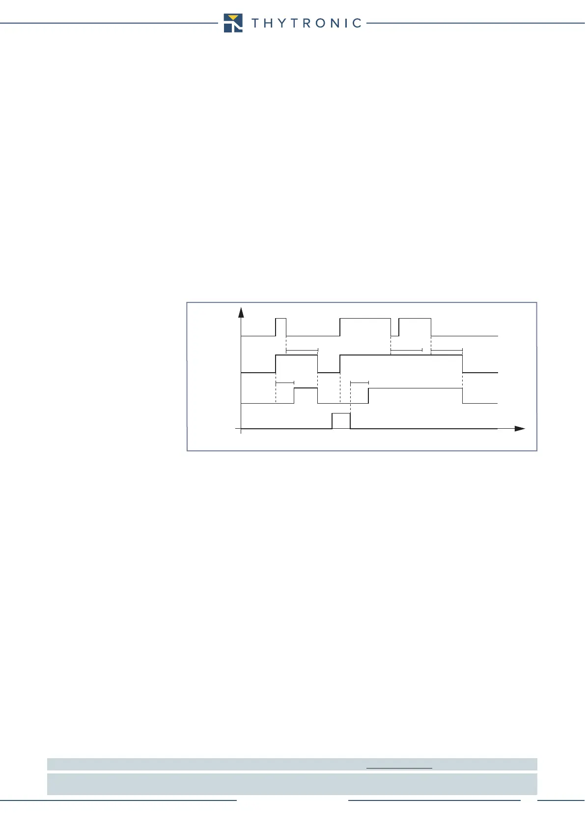
Timers-F67N.ai
IED> Start
IED> Trip
t
ED>
t
ED>
RESET
INPUT
t
ED>RES
t
ED>RES
t
ED>RES
t
IED> element timers - 67N
 Loading...


