Titan Implement, LLC 33 3515 Flex-Wing Rotary Cutter
(423) 334-0012 February 2020
6.2.4 Power Take-Off (PTO)
This rotary cutter is available in versions to operate at
a PTO speed of 540 RPM or 1000 RPM. Most tractors
operate at either 540 or a combination of 540 and 1000
RPM PTO speeds. The operating speed of the rotary
cutter and tractor can be determined by the number
of splines on the driveline yoke and PTO output shaft.
Those operating at 540 RPM will have a 6-spline shaft,
and those operating at 1000 RPM will have a 20 or
21-spline shaft.
Refer to the tractor Operator’s Manual for instructions
to change PTO speeds on models that operate at more
than one speed.
If operating an older model tractor where the tractor’s
transmission and PTO utilize one master clutch, an
over-running clutch must be used between the PTO
output shaft and the driveline of the rotary cutter. An
authorized tractor dealer can provide the over-running
clutch and its installation, if needed.
DO NOT use a PTO adapter to attach a non-
matching implement driveline to a tractor PTO. Use
of an adapter can double the operating speed of the
implement, resulting in excessive vibration, thrown
objects, and blade and implement failure. Adapter
use will also change the working length of the driveline
exposing unshielded driveline areas. Serious bodily
injury and/or equipment failure can result from using
a PTO adapter. Consult an authorized dealer for
assistance if the implement driveline does not match
the tractor PTO.
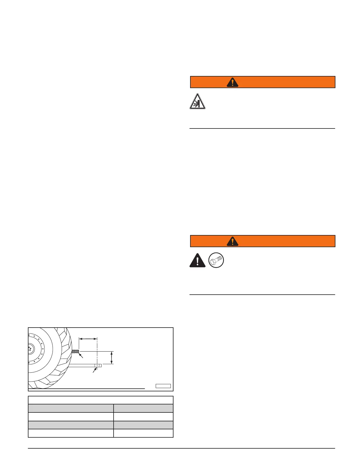
6.2.5 Drawbar
The distance between the drawbar hitch pin hole and
the end of tractor PTO shaft must be set according to
the PTO operating speed. The distance from the top of
the drawbar to the PTO shaft must be 8”. PTO damage
may occur if these dimensions vary more than 1”.
TI-00177
A
8”
Tractor PTO
Drawbar
Ground Level
DRAWBAR LENGTH CHART
PTO Dimension A
540 RPM 14”
1000 RPM, 21 spline, 1-3/8” shaft 16”
1000 RPM, 20 spline, 1-3/4” shaft 20”
6.3 Attaching to Tractor
Use caution when connecting the rotary cutter to the
tractor. The rotary cutter should be securely resting at
ground level or setting on blocks. Keep hands and feet
from under the deck and clear of pinch points between
the tractor drawbar and rotary cutter hitch.
Crush Hazard
Crush hazard between hitch and implement.
Do not allow anyone to stand between the
hitch and implement during hook-up
operations.
1. Use the jack to adjust the hitch to the height of the
tractor drawbar.
2. Board the tractor and start the engine. Back the
tractor up to the cutter hitch until the holes in the
drawbar and clevis are aligned.
3. Turn o the tractor engine and dismount.
4. Insert a 3/4” or larger high strength drawbar pin
through the clevis and drawbar holes and install
retaining pin. Do not use a homemade or shop
made pin.
OEM
Crush Hazard
Unexpected separation of the cutter
from the tractor can cause death or
serious injury. Use only an OEM high strength
drawbar pin. Do not use a homemade or shop made
pin.
5. Connect the hitch safety chain to the tractor drawbar
cage.
6. Retract the jack, remove the locking pin, move the
jack to its storage location on the cutter deck, and
secure it with the locking pin.
7. Pull back on collar (1) on the tractor end of the
driveline.
 Loading...