Installation
Fitting
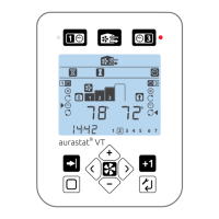
aurastat® VT
The unit is designed to be wall mounted or tted over a UK standard single gang recessed metal box. It should be sited in
a place that is visible and convenient for the householder. To t the unit, rst remove the front of the unit; The front of the
unit is removed by loosening a single screw on the bottom face to the unit, lifting the bottom of the front away from the
base and unhooking the top of the front from the base. Fix base to the wall (always use a xing suited to the wall type) or if
using a metal box using M3.5 raised countersunk machine screws.
Wiring Connections Access
aurastat® VT
The front of the unit is removed by loosening a single screw on the bottom face to the unit, lifting the bottom of the
front away from the base and unhooking the top of the front from the base. The base has a cable access knockout.
Communication Cable - Unshielded 4 Core 18-24AWG Stranded, Tinned Copper must be zip tied to the loop provided on
the front cover. The wiring connections are mounted on the circuit board in the front of the unit.
HRV
Refer to the Product Manual for the specic unit for information.
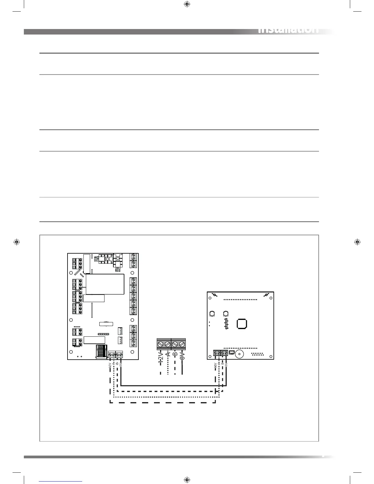
Wiring Diagram
aurastat® VT to HRV connection wiring
aurastat
®
HRV
7