Hardware Version : 5.02 Document Version : 1.0.
TECHMAN ROBOT INC. 5F., No. 58-2, Huaya 2nd Rd., Guishan Dist., Taoyuan City, 333411 , Taiwan
24
Torque specifications for Joint screws
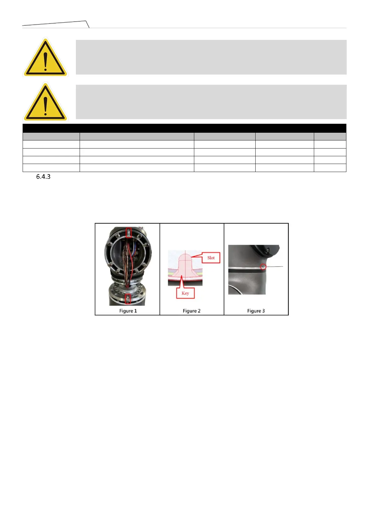
When assembling the joint, to ensure the correct installation orientation, it is necessary to interlock the
key and slot between the joints (refer to Figure 1) (see Figure 2). Operators can visually align the holes or
insert a Ø1.9mm pin into the hole to verify proper installation (see Figure 3). If the hole of two joints are
not in the same direction, or if misalignment prevents the insertion of the locating pin, do not proceed
with further assembly.
DANGER: Repeated use of disassembled screws is prohibited, as the screw adhesive on the
screws will become ineffective, and the repeated use will increase unforeseen risks.
DANGER: Tighten the joint screws according to the specified torque value provided below.