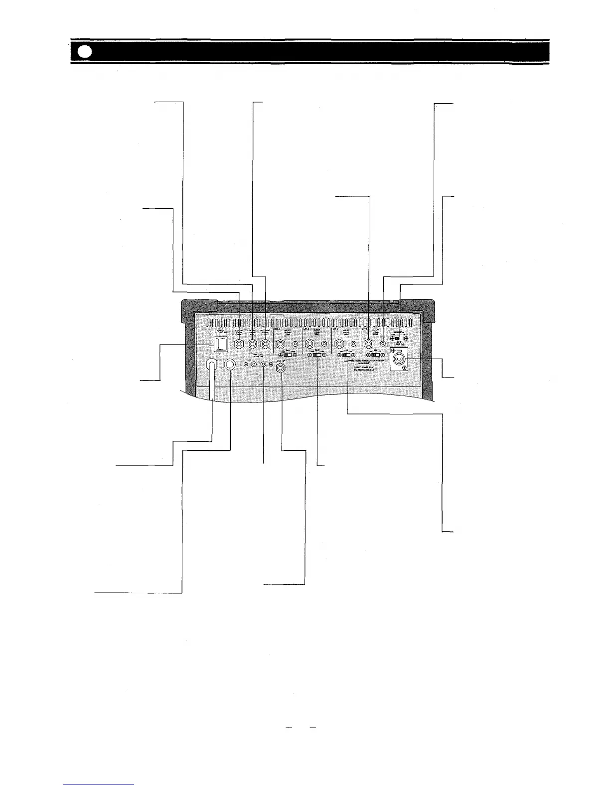
Rear Panel
Effect Return Jack [EFF RET]
This 1/4" phone jack is used in
conjunction with the Effect Send
jack to connect an outboard
effects device (i.e, delay or re-
verb) to the KD-1. The Effect
Return jack should be connected
to the output of the effect. Nomin-
al input level is -20dB with an
impedance of 10k ohms.
Aux Input Jack [AUX IN]
The unbalanced 1/4" phone jack
have a nominal input level of
-20dB and an impedance of 10k
ohms.
Effect Send Jack [EFF SEND]
This 1/4" phonejack is used in
conjunction with the Effect Re-
turn jack to connect an outboard
effects device (i.e, delay or re-
verb) to the KD-1. The Effect Send
jack should be connected to the
input of the Effect. Nominal out-
put level is -l0dB with an impe-
dance of 1k ohms.
1/4" Phone Channel Input
[INPUT]
This jack is a standard, unba-
lanced 1/4" phone jack, with a
nominal level of -30dB and an
impedance of 100k ohms. When a
plug is inserted into the 1/4" input
jack, the corresponding RCA pin
jack is automatically switched
out of the input circuitry.
RCA Channel Input [INPUT]
The RCA pin input jack is unba-
lanced, with a nominal level of
— 30dB and an impedance of 100k
ohms.
Phantom Power On/Off switch
[PHANTOM]
This switch alternately turns
"on" and "off the phantom pow-
er (48V DC) for the XLR connector
assigned to Channel 1. The
switch should remain in the off
position when a condenser type
mic is not in
use.
Power Switch [POWER]
The power switch is a three-
position type with the middle
position being the "off' position.
The KD-1 should be operated in
the switch position which pro-
duces the lowest amount of sys-
tem
hum.
AC Power Cord
The power cord is of the three-
wire type with proper grounding
facilities built-in. (6ft.)
Caution — The ground pin
should not be removed under any
circumstances. If the KD-1 must
be used without proper ground-
ing facilities, a suitable grounding
adapter should be utilized. Op-
eration of the KD-1 with proper
grounding techniques will result
in less system noise and greatly
reduced shock hazard.
AC
Fuse
Warning: To avoid possible
equipment damage and/or per-
sonnel injury, the fuse should
always be replaced with same
type and rating. Using improper
fuses will also void the warranty.
The KD-1 should always be dis-
connected from AC outlet prior to
changing fuses. If fuse repeatedly
fails, the unit should be referred
to qualified service personnel for
repair.
Recording Outout Jacks
[RECOUT]
The unbalanced RCA pin jacks
have a nominal output level of
-10dB and an impedance of 1k
ohms. The Recording Outputs are
pre-fader signals for connection
to tape recorders. Any change in
the level of the System Level
control will not alter the level of
the recording outputs.
Speaker Jack [EXT. SP]
The external speaker output is a
standard 1/4" phone jack. Speaker
cables (recommend at least #18
gauge wire) should be connected
between the KD-1 and the speaker
systems prior to applying AC
power to the unit. When a plug is
inserted into the external speaker
jack, the internal speaker is auto-
matically switched off.
Caution — The KD-1 should nev-
er be operated into less than an 8-
ohm speaker load.
Input Level Selector [PAD]
The slide switch provides 30dB
attenuation for the 1/4" Input
Jack, and RCA pin Input Jack at
the "30dB" position. The correct
setting should be made according
to the output level of the equip-
ment connected. For example, an
instrument with a "HOT" output
may overload the input circuitry,
resulting in a distorted or "FUZ-
ZY" sound.
Balanced XLR Microphone Input
[MIC]
The XLR-type microphone input
connector (channel 1 only) is
electronically balanced with a
nominal level of -60dB and an
input impedance of 1k ohms.
Phantom powering is provided
for use with condenser-type mic-
rophones (see PHANTOM). The
microphone input is automatical-
ly disconnected when either the
corresponding RCA Pin jack or
the 1/4" phone jack is used.
Effects ON/OFF Switch [EFF]
The slide switches provide quick
connects or disconnects of indi-
vidual channel input signals
(post-fader) to the effect buss, and
will thus turn the reverb/effect on
or off on that channel.
4