20
Chapter 4 Data Communications Interface
The MultiLoad II/ RCU II has four (4) communications ports (see Figure3.3), each with a specific
purpose. The following section provides the information required to select and make the wiring
connections to the ports:
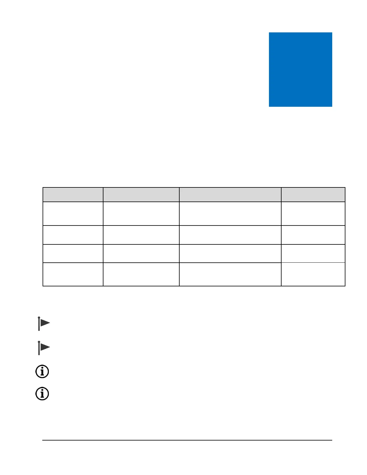
FCM I / FCM II / PCM
Communication
Host Communication (TMS) /
Printer
RS-232 or RS-485 (2 wire)
Ticket Printer/Data Logger
If a service loop is used, the maximum wire length in the service loop should not exceed
3 inches [75mm].
Separate AC and DC wiring by at least 3 inches [75mm]. Do not allow excess wire in the
service loop to overhang printed circuit board.
Default settings in MultiLoad are: COM O – FCM ; COM 1- HOST , and COM2 – NA.See
the user guide for more details
Only one port may be defined as an FCM, Print or Alibi Log, otherwise, a ‘Port Usage
Conflict(s)’ message will display upon re-boot. See the user guide for more details