InstallingtheGroomer
DriveSystem
PreparingtheCuttingUnit
Important:Readtheseinstructionsthoroughly
beforesettinguporoperatingthegroomer.
Failingtofollowsetuporoperatinginstructionsin
thismanualmayresultindamagetothecutting
unitand/orthegroomerortheturf.
Note:Determinetheleftandrightsidesofthe
machinefromthenormaloperatingposition.
1.Separatethecuttingunitfromthetractionunit.
RefertotheOperator'sManualforprocedure.
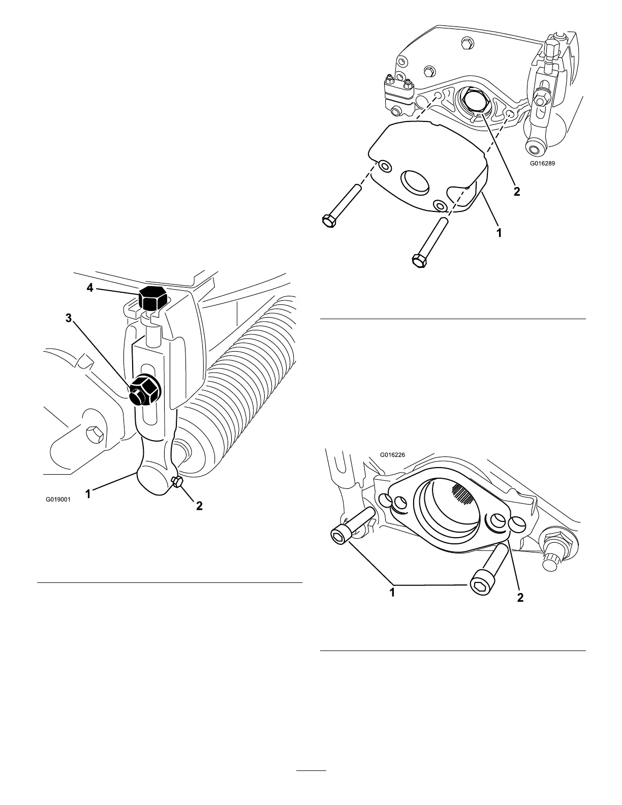
2.Loosenthescrewssecuringeachendofthe
frontrollertotheheight-of-cutarms(Figure1).
g019001
Figure1
1.Height-of-cutarm
3.Plowbolt,washer,and
locknut
2.Roller-mountingscrew4.Adjustingscrew
3.Removetheplowbolts,washers,andlocknuts
securingtheheight-of-cutarmstoeachendof
cuttingunit(Figure1).Removetheheight-of-cut
armsandrollerassembly.
Note:Retainallpartsforuseifyoueverremove
thegroomer.
4.Removetheheight-of-cutadjustingscrewsfrom
theheight-of-cutarms(Figure1).
5.Removethe2boltsandnutssecuringthe
counterweighttotherightendofthecuttingunit.
Removethecounterweight(Figure2).
g016289
Figure2
1.Counterweight
2.Bearingnut
6.Removethebearingnutfromthereelshaft
(Figure2).
7.IfthekitisbeinginstalledonaTriFlex3300,
3320,3400,or3420machine,,removethe2
boltssecuringthemotormounttotheleftend
ofthecuttingunit.Removethemotormount
(Figure3).
Note:Retaintheparts.
g016226
Figure3
1.Bolt2.Motormount
3