EasyManua.ls Logo

Toro Groundmaster 4300-D Series - User Manual

Toro Groundmaster 4300-D Series
8 pages
Print Icon
To Next Page IconTo Next Page
Loading...
FormNo.3425-668RevA
DriveplateKit
Reelmaster
®
5410/5510/5610-DorGroundsmaster
®
4300-DSeries
TractionUnitwithYanmarEngine
ModelNo.138-6973
InstallationInstructions
WARNING
CALIFORNIA
Proposition65Warning
UseofthisproductmaycauseexposuretochemicalsknowntotheStateofCalifornia
tocausecancer,birthdefects,orotherreproductiveharm.
LooseParts
Usethechartbelowtoverifythatallpartshavebeenshipped.
Description
Qty.
Use
Nopartsrequired
Preparethemachine.
Nopartsrequired
Removethehoodsaddleanddrive-lineguard.
Nopartsrequired
Removethedriveshaftandywheel-adapterplate.
Flywheel-adapterplate1
Backupplate1
Capscrew(3/8x1inch)
6
Flangelocknut(3/8inch)
6
Replacetheywheel-adapterplate.
Flange-headcapscrew8
Backupring2
Installthedriveshaftandywheel-adapterplate.
Nopartsrequired
Installthedrive-lineguardandhoodsaddle.
Nopartsrequired
Finishthekitinstallation.
PreparingtheMachine
CAUTION
Ifyouleavethekeyintheswitch,someone
couldaccidentlystarttheengineand
seriouslyinjureyouorotherbystanders.
Removethekeyfromtheswitchbeforeyou
performanymaintenance.
1.Parkthemachineonalevelsurface,engage
theparkingbrake,lowerthecuttingunits,shut
offtheengine,removethekey,andwaitforall
movementtostopbeforeleavingtheoperator’s
seat.
2.Unlatchandtiptheoperator’sseat.
3.Unlatchandopenthehood.
RemovingtheHoodSaddle
andDrive-LineGuard
1.Liftthehoodsaddlefromthesaddlebrackets,
andremovehoodsaddlefromthemachine
(Figure1).
©2018—TheToro®Company
8111LyndaleAvenueSouth
Bloomington,MN55420
Registeratwww.T oro.com.
OriginalInstructions(EN)
PrintedintheUSA
AllRightsReserved
*3425-668*A
Question and Answer IconNeed help?

Do you have a question about the Toro Groundmaster 4300-D Series and is the answer not in the manual?

Summary

Driveplate Kit Installation Instructions

Loose Parts

Lists all parts included in the kit for verification.

Preparing the Machine

Outlines safety and preparatory steps before starting the installation.

Removing the Hood Saddle and Drive-Line Guard

Details the process of removing the hood saddle and drive-line guard.

Removing the Driveshaft and Flywheel-Adapter Plate

Disconnecting the Driveshaft from the Hydraulic Pump

Explains how to detach the driveshaft from the hydraulic pump.

Removing the Driveshaft and Flywheel-Adapter Plate from the Engine

Details the process of removing the driveshaft assembly from the engine.

Replacing the Flywheel-Adapter Plate

Removing the Driveshaft from the Flywheel-Adapter Plate

Describes how to separate the driveshaft from the adapter plate and backup plate.

Assembling the Driveshaft and Flywheel-Adapter Plate

Assembling the Driveshaft to the Flywheel-Adapter Plate

Details connecting the driveshaft to the flywheel-adapter plate and backup plate.

Assembling the Driveshaft to the Hydraulic Pump

Details connecting the driveshaft yoke to the hydraulic pump shaft.

Installing the Driveshaft and Flywheel-Adapter Plate to the Engine

Outlines applying thread locker and attaching the assembly to the engine.

Installing the Drive-Line Guard and Hood Saddle

Finishing the Kit Installation

Describes final checks and closing the machine's hood and seat.

Overview

This document describes the installation of a Driveplate Kit, Model No. 138-6973, for Toro Reelmaster® 5410/5510/5610-D or Groundsmaster® 4300-D Series Traction Units equipped with Yanmar Engines. The kit is designed to facilitate the replacement or installation of the flywheel-adapter plate and associated drive components, ensuring proper power transmission from the engine to the hydraulic pump.

Function Description

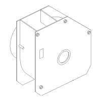
The Driveplate Kit serves as a crucial interface between the engine's flywheel and the hydraulic pump, which powers the traction unit's various functions. The flywheel-adapter plate, a central component of this kit, connects the engine's rotational output to the driveshaft. The driveshaft, in turn, transmits this power to the hydraulic pump. This setup is essential for the operation of the Reelmaster and Groundsmaster series machines, enabling their traction, cutting unit operation, and other hydraulic functions. The kit includes components necessary for securely mounting the driveshaft and flywheel-adapter plate, ensuring efficient and reliable power transfer. The installation process involves removing existing components, replacing the flywheel-adapter plate, and reassembling the driveshaft and associated guards.

Important Technical Specifications

The kit includes a specific set of components designed for precise fit and function within the specified Toro machines. Key components and their quantities are:

  • Flywheel-adapter plate: 1
  • Backup plate: 1
  • Capscrew (3/8 x 1 inch): 6
  • Flange locknut (3/8 inch): 6
  • Flange-head capscrew: 8
  • Backup ring: 2

Torque specifications are critical for proper installation and long-term reliability:

  • Flange-head capscrews (securing flywheel-adapter plate to engine): 23 to 28 N·m (17 to 21 ft lb).
  • Capscrews and lock nuts (securing driveshaft to flywheel-adapter plate): 37 to 43 N·m (28 to 32 ft lb).
  • Locknuts (securing driveshaft yoke to hydraulic pump shaft): 20 to 25 N·m (175 to 225 in-lb).

An owner-supplied material, Permatex® high-strength thread locking compound Part No. 24010, is required for the flange-head capscrews that secure the flywheel-adapter plate to the engine's flywheel. This ensures the fasteners remain secure under operational vibrations and stresses.

Usage Features

The installation process is detailed, guiding the user through several stages:

  1. Preparing the Machine: This initial step emphasizes safety by requiring the machine to be parked on a level surface, the parking brake engaged, cutting units lowered, engine shut off, key removed, and all movement stopped. The operator's seat is unlatched and tipped, and the hood is unlatched and opened to provide access to the engine compartment.
  2. Removing the Hood Saddle and Drive-Line Guard: The hood saddle and drive-line guard are removed to expose the driveshaft and flywheel-adapter plate. This involves lifting the hood saddle and then removing two flange nuts that secure the drive-line guard.
  3. Removing the Driveshaft and Flywheel-Adapter Plate: This is a multi-step process that differentiates between machines with and without backup rings.
    • Disconnecting from Hydraulic Pump: Two flange locknuts and two capscrews are removed to separate the driveshaft yoke from the hydraulic pump shaft.
    • Removing from Engine (without Backup Rings): Eight flange-head capscrews are removed to detach the flywheel-adapter plate and driveshaft from the engine's flywheel. The removed capscrews are discarded.
    • Removing from Engine (with Backup Rings): Eight flange-head capscrews and two backup rings are removed to detach the flywheel-adapter plate, backup rings, and driveshaft from the engine's flywheel. The removed capscrews and backup rings are discarded.
  4. Replacing the Flywheel-Adapter Plate: This section details the separation of the driveshaft from the old flywheel-adapter plate and backup plate. Six capscrews and six flange locknuts are removed, and the old flywheel-adapter plate and backup plate are discarded.
  5. Assembling the Driveshaft to the Flywheel-Adapter Plate: The new flywheel-adapter plate and backup plate are assembled to the driveshaft using the new capscrews and flange locknuts, tightened to the specified torque.
  6. Assembling the Driveshaft and Flywheel-Adapter Plate to the Engine: This critical step involves applying thread locking compound to the flange-head capscrews. The two new backup rings and the assembled flywheel-adapter plate are then secured to the engine's flywheel using the eight new flange-head capscrews, tightened to the specified torque.
  7. Assembling the Driveshaft to the Hydraulic Pump: The driveshaft yoke is aligned with and slid onto the hydraulic pump shaft. It is then secured with the previously removed capscrews and flange nuts, tightened to the specified torque.
  8. Installing the Drive-Line Guard and Hood Saddle: The drive-line guard is reinstalled, aligning its holes with the capscrew in the guard bracket and heat shield, and secured with the previously removed flange nuts. The heat shield is tilted down to prevent contact with the rotating driveshaft. Finally, the hood saddle is reassembled onto the saddle brackets.
  9. Finishing the Kit Installation: The seat is tilted down and latched, and the hood is closed and secured.

Maintenance Features

The document primarily focuses on installation rather than ongoing maintenance. However, it implicitly highlights several maintenance-related aspects:

  • Part Replacement: The kit itself is a replacement part, indicating that the flywheel-adapter plate and associated fasteners are subject to wear and may require periodic replacement.
  • Torque Specifications: The emphasis on precise torque values for all fasteners is a critical maintenance practice. Correct torque ensures components are securely fastened, preventing loosening due to vibration and reducing the risk of premature wear or failure.
  • Thread Locking Compound: The requirement for Permatex® high-strength thread locking compound on specific fasteners underscores the importance of preventing fastener loosening in high-vibration environments, a common issue in heavy machinery.
  • Discarding Old Parts: The instruction to discard old flange-head capscrews, backup rings, and the old flywheel-adapter plate/backup plate indicates that these are single-use components or components that should not be reused after removal, ensuring that new, uncompromised parts are used for the installation.
  • Safety Precautions: The initial safety warnings regarding removing the key and waiting for movement to stop before maintenance are fundamental to safe operation and maintenance of the machine. The California Proposition 65 warning also serves as a reminder of potential chemical exposures that might require specific handling or protective measures during maintenance.

Toro Groundmaster 4300-D Series Specifications

General IconGeneral
BrandToro
ModelGroundmaster 4300-D Series
CategoryLawn Mower Accessories
LanguageEnglish

Related product manuals