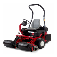
Greensmaster 3250--D
Page 5 -- 16
Electrical System
Diode Circuit Boards
The Greensmaster 3250--D electrical system uses two
(2) diode circuit boards that are inserted into wire har-
ness connectors. Each of these circuit boards contain
four (4) diodes. The diodes are used for circuit protec-
tion from inductive voltage spikes and for safety circuit
logic.
Applydielectricgrease(Toropartnumber 107--0342)to
circuit board contacts whenever the circuit board is
installed into the wire harness.
NOTE: The Greensmaster 3250--D does not use
diodes D1--B or D2--B.
DiodeD1--AallowscurrentflowtosolenoidS2whenthe
lower relay is energized. It also prevents current flow to
solenoid S4 when the raise relay is energized.
Diode D1--C prevents a negative spike from damaging
the mow sensor and backlap switch by allowing a
ground path for the mow relay when it de--energizes.
DiodeD1--DallowscurrentflowtosolenoidS2whenthe
raise relay is energized. It also prevents current flow to
solenoid S4 when the lower relay is energized.
Diode D2--A prevents a negative spike from damaging
theneutralsensor and seatswitchbyallowingaground
path for the run relay when it de--energizes.
Diode D2--C maintains current flow to the joystick relay
after the momentary lower switch of the joystick opens.
Diode D2--D allows the engine to start only with the
functional control lever in NEUTRAL ( neutral sensor
closed).Also,itallowstheengineto continuetorunwith
either the functional control lever in NEUTRAL (neutral
sensor closed) or the operator sitting in the seat (seat
switch closed) with the parking brake released (parking
brake sensor closed).
Testing
Thec ircuitboarddiodescanbeindividuallytestedusing
a digital multimeter (ohms setting) and the table to the
right. If any of the diodes on the circuit board are dam-
aged, the diode circuit board must be replaced.
Figure 15
DIODE
CIRCUIT
BOARD
B
C
D
A
Figure 16
DIODE
DIAGRAM
A
B
C
D
Red Lead (+)
on Terminal
Black Lead (--)
on Terminal
Continuity
H A YES
A H NO
G B YES
B G NO
F C YES
C F NO
E D YES
D E NO

 Loading...