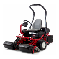
Greensmaster 3250--D Page 6 -- 17 Chassis
Disassembly
1. Park machine on a level surface. Make sure engine
is off and parking brake is engaged.
2. Remove center cutting unit from lift arm.
3. DisassemblecenterliftarmasneededusingFigures
13 and 14 as guides.
Assembly
1. Ifliftframe(item25inFig.13)wasremovedfromma-
chine:
A. Adjust eccentric bushings (item 22 in Fig. 13) as
neededsothatliftframeislevelwhentheliftframeis
in the raised position.
B. Installthrustwashers(item12inFig.13)asneed-
ed so that lift frame is centered between the front
wheelmountswhentheliftframeisintheraisedposi-
tion.
2. Assemble center lift arm using Figures 13 and 14 as
guides.
A. If clevis (item 31 in Fig. 13) was removed from
centerliftframe,torquecapscrewfrom67to83ft--lb
(91 to 112 N--m).
B. If pull frame (item1inFig.14) was removed from
clevis on lift frame, torque cap screw from 67 to 83
ft--lb (91 to 112 N--m).
3. Attach cutting unit to lift arm.
4. Check thatwhenraisedtothetransport position,the
cutting unit is secured by the transport plate. If neces-
sary, loosen two (2) cap screws (item 30 in Fig. 13) and
reposition transport plate.
1. Pull frame
2. Pivot spacer
3. Bushing
4. Clevis
5. Cap screw
6. Lock nut
Figure 14
1
2
3
5
6
4
3
67 to 83 ft--lb
(91 to 112 N--m)
Chassis

 Loading...