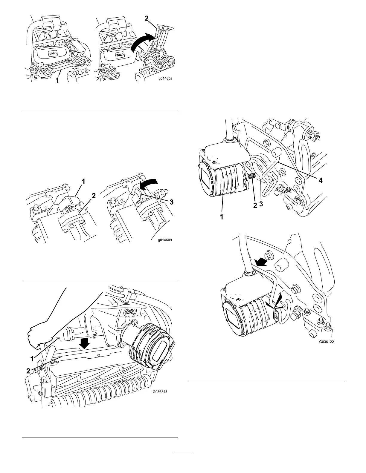
g014602
Figure52
1.Footrest—closed2.Footrest—open
3.Positionthecuttingunitunderthecenter
suspensionarm.
4.Withthelatchesonthesuspension-armbar
pointingup(i.e.,open)(Figure53),pushthe
suspensionarmdownsothatthebartsover
thebaracrossthetopofthecuttingunit(Figure
54).
g014609
Figure53
1.Latch—closedposition3.Latch—openposition
2.Suspension-armbar
g036343
Figure54
1.Suspension-armbar2.Cutting-unitbar
5.Closethelatchesdownandaroundthe
cutting-unitbarandlocktheminplace(Figure
53).
Note:Youcanhearaclickandfeelwhenthe
latchesareproperlylockedinplace.
6.Coatthesplineshaftofthecuttingunitmotor
withcleangrease(Figure55).
7.Insertthemotorintotheleftsideofthecutting
unit(asviewedfromtheoperator'sposition)and
pullthemotorretainingbaronthecuttingunit
towardthemotoruntilyouhearaclickfromboth
sidesofthemotor(Figure55).
g036122
Figure55
1.Reelmotor
3.Cavity
2.Splineshaft
4.Motor-retainingbar
8.Mountagrassbasketontothebaskethookson
thesuspensionarm.
9.Repeatthisprocedurefortheothercuttingunits.
10.Connectthecuttingunitpowerdisconnect
couplers;refertoCuttingUnitPowerDisconnect
Connectors(page22).
48