FuelSystem
Maintenance
DANGER
Undercertainconditions,dieselfuelandfuel
vaporsarehighlyammableandexplosive.Are
orexplosionfromfuelcanburnyouandothersand
cancausepropertydamage.
•Useafunnelandllthefueltankoutdoors,in
anopenarea,whentheengineisoffandiscold.
Wipeupanyfuelthatspills.
•Donotllthefueltankcompletelyfull.Addfuel
tothefueltankuntilthelevelistothebottom
ofthellerneck.
•Neversmokewhenhandlingfuel,andstayaway
fromanopenameorwherefuelfumesmaybe
ignitedbyaspark.
•Storefuelinaclean,safety-approvedcontainer
andkeepthecapinplace.
ServicingtheWaterSeparator
ServiceInterval:Every400hours
Every400hours
Drainwaterorothercontaminantsfromwaterseparator
(Figure42)daily.
1.Placeacleancontainerunderthefuellter.
2.Loosenthedrainplugonthebottomofthelter
canister.
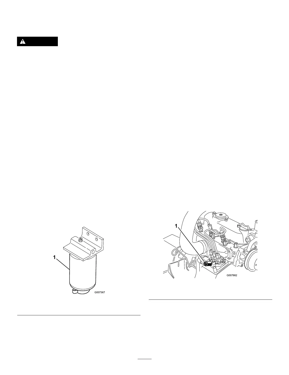
Figure42
1.Waterseparatorltercanister
3.Cleantheareawheretheltercanistermounts.
4.Removetheltercanisterandcleanthemounting
surface.
5.Lubricatethegasketontheltercanisterwithcleanoil.
6.Installtheltercanisterbyhanduntilthegasket
contactsmountingsurface,thenrotateitanadditional
1/2turn.
7.Tightenthedrainplugonthebottomofthelter
canister.
CleaningtheFuelTank
ServiceInterval:Every2years
Drainandcleanfueltankevery2years.Also,removeand
cleanthein-linestrainersafterdrainingthetank.Useclean
dieselfueltoushoutthetank.
Important:Drainandcleanthetankifthefuelsystem
becomescontaminatedorifthemachineistobestored
foranextendedperiod.
FuelLinesandConnections
ServiceInterval:Every400hours
Checkthefuellinesandconnections.Inspectthemfor
deterioration,damage,chafng,orlooseconnections.
BleedingtheFuelSystem
1.Parkthemachineonalevelsurface.Ensurethatthe
fueltankisatleasthalffull.
2.Unlatchandraisethehood.
3.Placearagundertheair-bleedscrewonthe
fuel-injectionpumpandopenit(Figure43).
Figure43
1.Fuel-injectionpumpbleedscrew
4.TurnthekeyintheignitionswitchtotheOnposition.
Theelectricfuelpumpwillbeginoperation,thereby
forcingairoutaroundtheairbleedscrew.
40