SpacersBelowCastorArm Height-of-Cut
Setting
FrontRear
38mm(1–1/2
inches)
00
50mm(2inches)
11
63mm(2–1/2
inches)
22
76mm(3inches)
33
89mm(3–1/2
inches)
44
102mm(4inches)
55
114mm(4–1/2
inches)
66
Starttheengineandraisethecuttingunitsothatthe
height-of-cutcanbechanged.Stoptheengineafterthe
cuttingunitisraised.
25mm(1inch)height-of-cutcanbeattainedbymodifying
thecastorforksasfollows:
1.Removethefrontandrearcastorforksfromthecutting
deckandremovethewheelsfromtheforks.
2.Drilloutthe0.438inchdiameterholes(Figure11&
Figure12)ineachsideofthecastorforksto0.50inch
or0.516inchdiameter.
3.Usingthenewholes,installthecastorwheelsonthe
forksandinstalltheforksonthedeck.
Note:Theheight-of-cutdecalwillnowbeoffby
13mm(1/2inch)forspacerplacementandthe
height-of-cutwillbe25to102mm(1to4inches).
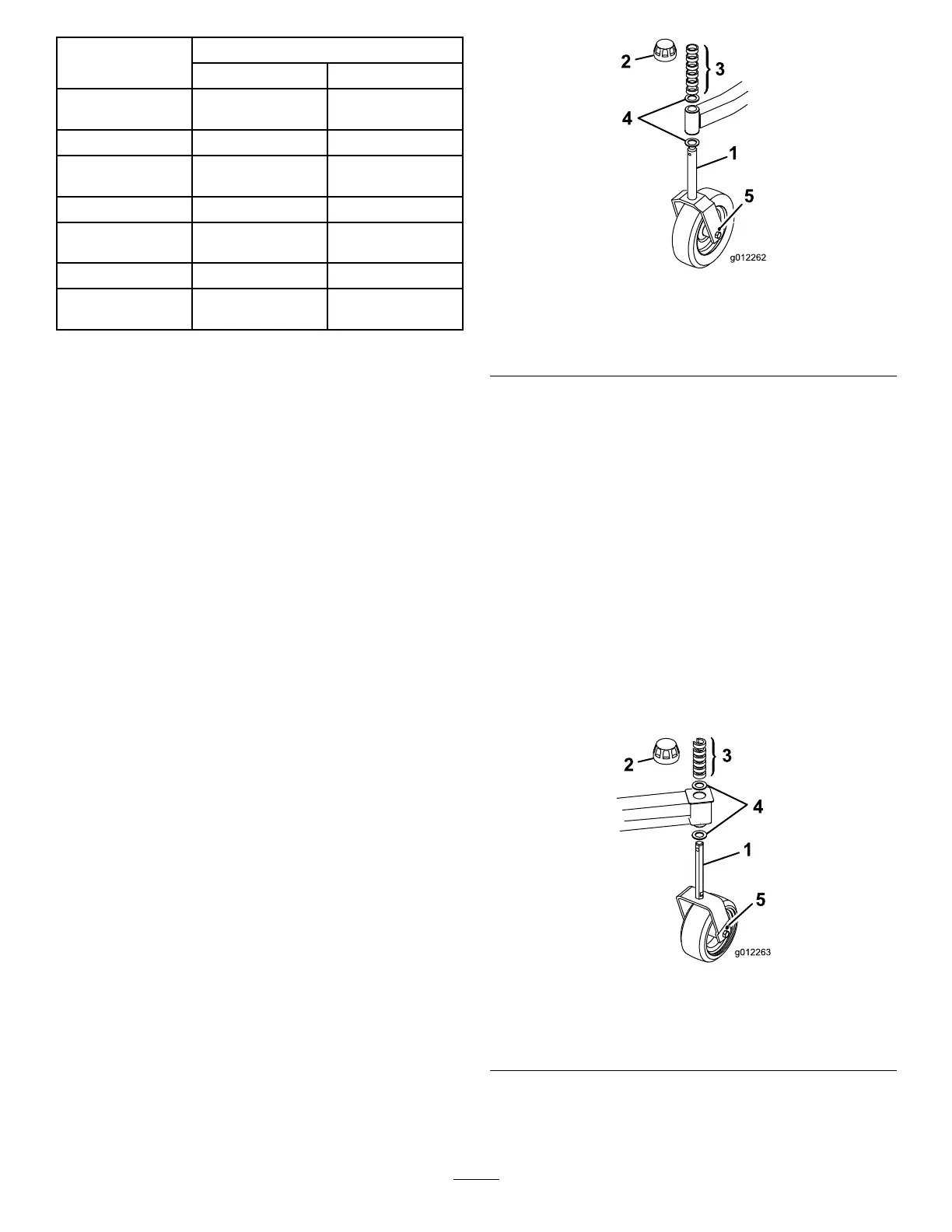
FrontCastorWheels
1.Removethetensioningcapfromthespindleshaftand
slidethespindleoutofthefrontcastorarm.Remove
thewasherfromthespindleshaft.Slidethespacers
ontothespindleshafttogetdesiredtheheight-of-cut,
thenslidethewasherontotheshaft(Figure11).
2.Pushthecastorspindlethroughthefrontcastorarm,
installtheotherthrustwasherandremainingspacers
ontothespindle,andinstallthetensioningcapto
securetheassembly(Figure11).
Figure11
1.Frontcastorwheel4.Thrustwashers
2.Tensioningcap5.0.438inchdiameterhole
3.Spacers
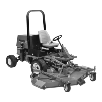
RearCastorWheels
1.Removethetensioningcapfromthespindleshaft
(Figure12).
Note:Therearcastorforkassemblydoesnotneed
toberemovedfromthecastorarmtochangethe
height-of-cut.
2.RemoveoraddtheC-shapedspacersatthenarrow
portionofthespindleshaft,belowthecastorarm,to
getthedesiredheight-of-cut(Figure12).Makesure
thatthethrustwashers-notthespacers-contactthetop
andbottomofthecastorarm.
3.Installthetensioningcaptosecuretheassembly
(Figure12).
4.Ensurethatallfourcastorwheelsaresetatthesame
height-of-cut.
Figure12
1.Rearcastorwheel4.Thrustwashers
2.Tensioningcap5.0.438diameterhole
3.Spacers
14