towardyoutothemostcomfortablepositionandthen
releasethepedal.
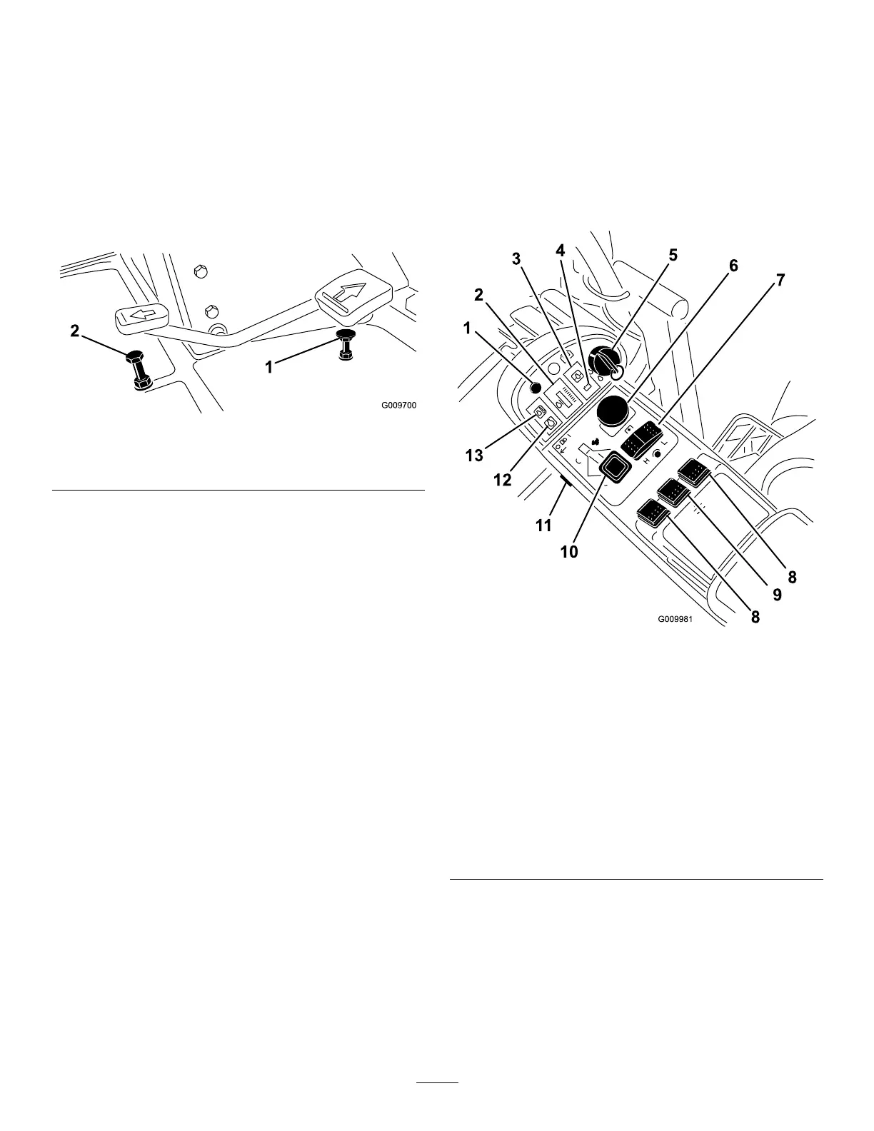
SpeedLimiterScrews
Adjustthescrew(s)(Figure9)tolimittheamountthe
tractionpedalcanbedepressedintheforwardorreverse
directiontolimitspeed.
Important:Thespeedlimiterscrewmuststopthe
tractionpedalbeforethepumpreachesfullstroke
ordamagetothepumpmayoccur.
Figure9
1.Forwardspeedlimiter
screw
2.Reversespeedlimiter
screw
DiagnosticLight
Thediagnosticlight(Figure10)willilluminateshoulda
systemfaultberecognized.
EngineCoolantTemperatureGauge
Duringnormaloperatingconditionsthegauge
(Figure10)shouldbeinthegreenrange.Checkthe
coolingsystemifthegaugegoestotheyelloworred
range.
EngineOilPressureWarningLight
Thelight(Figure10)illuminateswhentheengineoil
pressureisdangerouslylow.
ChargeIndicator
Thechargeindicator(Figure10)illuminateswhenthe
systemchargingcircuitmalfunctions.
KeySwitch
Thekeyswitch(Figure10)hasthreepositions:Off,
On/Preheat,andStart.
PTOSwitch
ThePTOswitch(Figure10)hastwopositions:Out
(start)andIn(stop).PullthePTObuttonouttoengage
thecuttingunitblades.Pushinthebuttontodisengage
thecuttingunitblades.
Hi-LoSpeedControl
Theswitch(Figure10)allowsthespeedrangetoincrease
fortransportofthemachine.Cuttingdeckswillnot
operateinhighrange.Also,thedeckscannotbelowered
fromthetransportpositionwhentheswitchisinthe
highrange.
Figure10
1.Diagnosticlight
8.Liftswitches(GM4700
only)
2.Enginecoolant
temperaturegauge
9.Liftswitch(GM4500and
4700)
3.Engineoilpressure
warninglight
10.Throttlecontrol
4.Chargeindicator
11.Lightswitch
5.Keyswitch
12.Glowplugindicatorlight
6.PTOswitch
13.Enginecoolant
temperaturewarning
light
7.Hi-Lospeedcontrol
LiftSwitches
Theliftswitches(Figure10)raiseandlowerthecutting
units.Presstheswitchesforwardtolowerthecutting
unitsandbackwardtoraisethecuttingunits.When
startingthemachine,withthecuttingunitsinthedown
position,presstheliftswitchdowntoallowthecutting
unitstooatandmow.
16