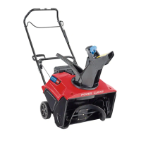
Figure9
1.Handgrip
3.1to2inches(3to5cm)
2.Auger/impellercontrol
lever
4.5inches(12.7cm)
Note:Thedistanceshouldbeapproximately5
inches(12.7cm).
4.Presstheauger/impellerdrivecontrolleverslowly
towardthehandgrip.
Note:Theamountofforceneededtocompressthe
leverincreasesnoticeablywhenyouremovetheslack
fromtheauger/impellerdrivebelt(approximately
1/2ofthelevermovement).Theadjustmentis
correctwhentheforcebeginstoincreaseandthe
distancebetweenthetopofthehandgripandthe
bottomoftheauger/impellerdrivecontrolleveris1
to2inches(3to5cm)asshowninFigure9.
Note:Iftheforcedoesnotnoticeablyincrease,
removethebeltcover(refertostep2ofReplacing
theTractionDriveBeltinMaintenance)andmeasure
2inches(5cm)abovethehandgripatthepoint
whereyouremovetheslackfromtheauger/impeller
drivebelt.
5.Toadjustthedistance:
A.Removetheclevispin.
B.Loosenthejamnut.
C.Threadtheclevisupordowntoincreaseor
decreasethedistancebetweenthetopofthe
handgripandthebottomoftheauger/impeller
drivecontrollever(Figure8).
6.Whentheadjustmentiscorrect,installtheclevispin
andsecureitinplacewiththecotterpin(Figure8).
7.Tightenthejamnuttosecuretheclevis(Figure8).
5.InstallingtheChuteControl
Rod
1
Chutecontrolrodassembly(rodandbracket,worm
gear,andbracket)
1
Carriagebolt
1Bellevillewasher
1Hexheadbolt
2Locknut
Procedure
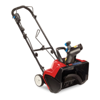
1.Assemblethechutecontrolbracketandrodtothe
leftsideofthehandlewiththeboltandthelocknut
asshowninFigure10.
Figure10
1.Chutecontrolbracketand
rod
2.Hexheadboltandlocknut
Note:Donottightenthelocknut.
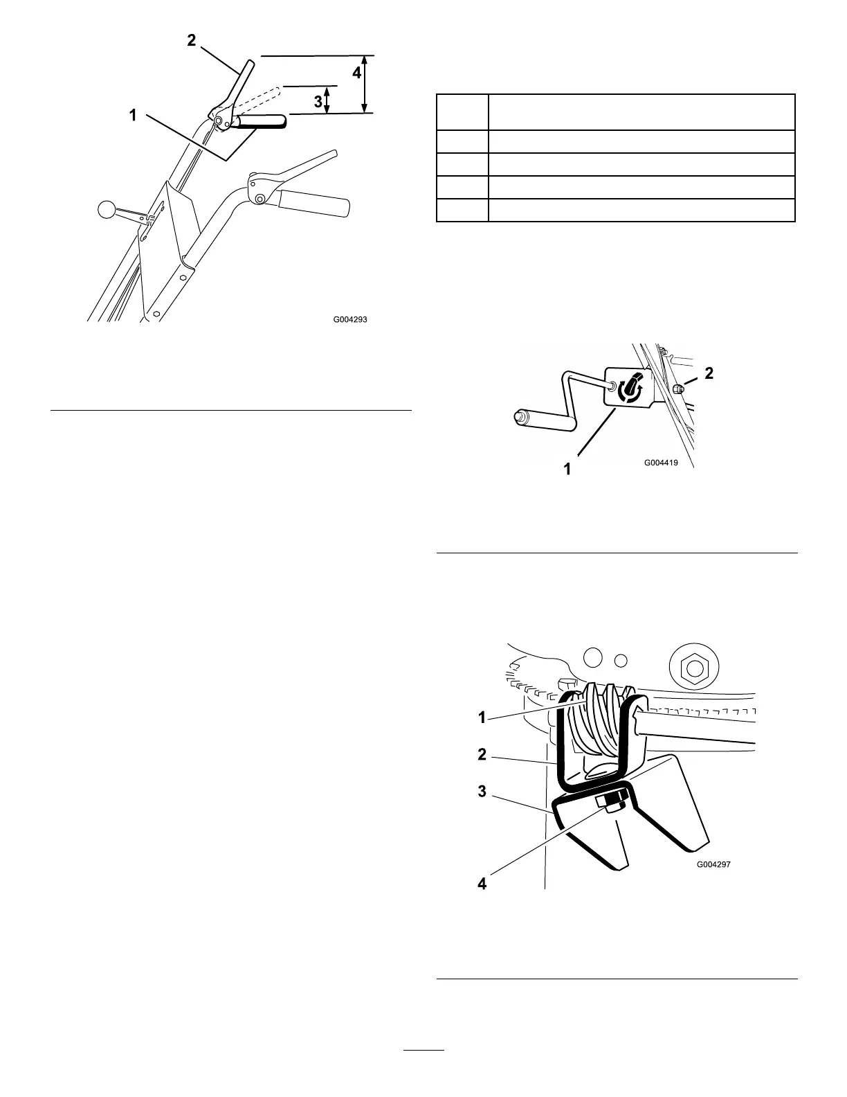
2.ApplyNo.2generalpurposegreasetotheworm
gear(Figure11).
Figure11
1.Wormgear
3.Mountingange
2.Bracket
4.Carriagebolt,Belleville
washer,andlocknut
10