2.Movethespeedselectorlever(Figure13)onthe
controlpaneltotheR(Reverse)position.
3.Installthespeedselectorrodintothespeedselector
arm,addaatwasherontheselectorrod,andsecure
itwithacotterpin(Figure6).
3.InstallingtheTractionRod
1Flangelocknut
Procedure
1.Threadtheangelocknut(angesideup)ontothe
bottomofthetractioncontrolrod,belowtheloop
inthelowertractionrod(Figure4).
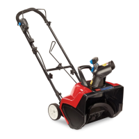
2.Adjustthe2angenutsupordownonthetraction
roduntilthedistancebetweenthetopofthe
handgripandthebottomofthetractioncontrol
leverisapproximately4-1/2inches(11.4cm)as
showninFigure7.
Figure7
1.Handgrip
3.1to2inches(3to5cm)
2.Tractioncontrollever
4.4-1/2inches(11.4cm)
3.Tightenthe2angenutsuntiltheyarengertight.
4.Movethespeedselectorlever(Figure13)intothird
gear.
Note:Ifthespeedselectorleverdoesnotmove
intothirdgear,adjustthespeedselectorbefore
continuing.RefertoAdjustingtheSpeedSelector
inMaintenance.
5.Slowlypullthesnowthrowerbackwardwhileslowly
pressingthetractioncontrollevertowardthe
handgrip.
Note:Theadjustmentiscorrectwhenthewheels
stoprollingbackwardandthedistancebetweenthe
topofthehandgripandthebottomofthetraction
controlleveris1to2inches(3to5cm)asshown
inFigure7.
6.Adjustthe2angenuts,ifnecessary,toobtainthe
properdistancebetweenthetopofthehandgripand
thebottomofthetractioncontrollever.
7.Tightentheangenutssecurely.
4.InstallingtheAuger/Impeller
DriveControlLinkage
1
Clevispin
1
Cotterpin
Procedure
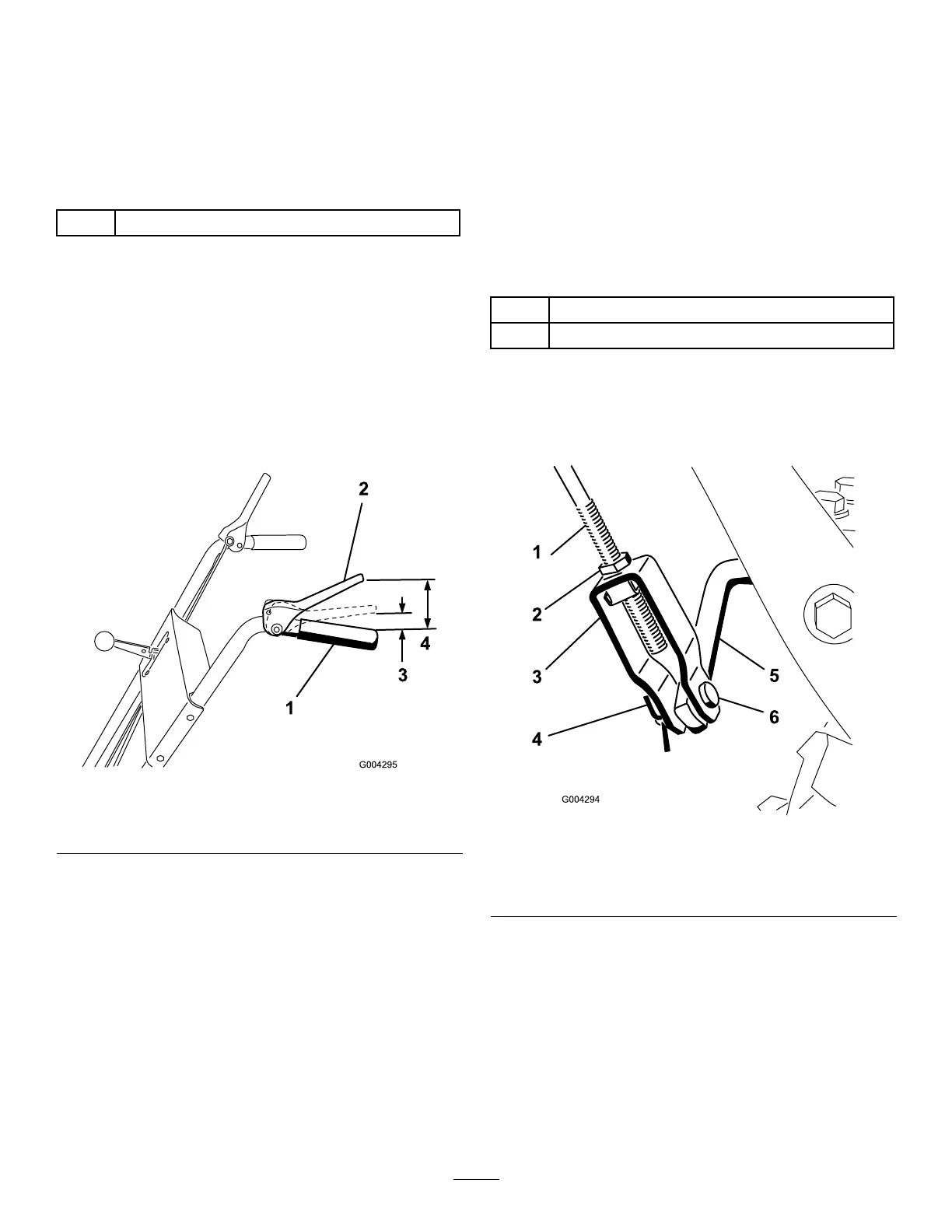
1.Loosenthejamnutabovetheclevisontheupper
controlrod(Figure8).
Figure8
1.Uppercontrolrod
4.Cotterpin
2.Jamnut5.Lowercontrolrod
3.Clevis6.Clevispin
2.Aligntheholesintheclevisandthelowercontrol
rodandinserttheclevispin(Figure8).
3.Checkthedistancebetweenthetopofthehandgrip
andthebottomoftheauger/impellerdrivecontrol
lever(Figure9).
9