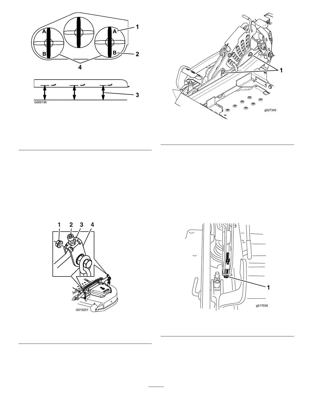
g009196
Figure114
1.7.6cm(3inch)atposition
Aiscorrect
3.Measureherefromthe
bladetiptothehard
surface
2.8.3cm(3-1/4inch)at
positionBiscorrect
4.MeasureatpositionAand
Bonbothsides
10.Fine-tunetheadjustmentnutonthefront
deck-liftassemblybyturningit(Figure115).
Note:T oincreasetheheight,turnthe
adjustmentnutclockwise;todecreasethe
height,turnthenutcounterclockwise.
Note:Ifthefrontdecklinksdonothaveenough
adjustmenttoachieveaccuratecutheight,you
canusethesingle-pointadjustmenttogain
moreadjustment.
g010251
Figure115
1.Whizlocknut3.Jamnut
2.Adjusterscrew4.Yoke
11.Toadjustthesingle-pointsystem,loosenthe
2boltsatthebottomoftheheight-of-cutplate
(Figure116).
g027345
Figure116
1.Boltsatthebottomoftheheight-of-cutplate
12.Ifthedeckistoolow,tightenthe
single-point-adjustmentboltbyrotatingit
clockwise.Ifthedeckistoohigh,loosen
thesingle-point-adjustmentboltbyrotatingit
counterclockwise(Figure117).
Note:Loosenortightenthesingle-point
adjustmentboltenoughtomovethe
height-of-cutplatemountingboltsatleast1/3
thelengthoftheavailabletravelintheirslots.
Thisregainssomeupanddownadjustmenton
eachofthe4decklinks.
g017036
Figure117
1.Single-pointadjustmentbolt
13.Tightenthe2boltsatthebottomofthe
height-of-cutplate(Figure116).
Note:Inmostconditions,thebackbladetip
shouldbeadjusted6.4mm(1/4inch)higher
thanthefront.
73