ChargingtheBattery
ServiceInterval:Beforestorage—Chargethebattery
anddisconnectthebatterycables.
1.Removethebatteryfromthechassis;referto
RemovingtheBattery(page42).
2.Chargethebatteryforaminimumof1hourat
6to10amps.
Note:Donotoverchargethebattery.
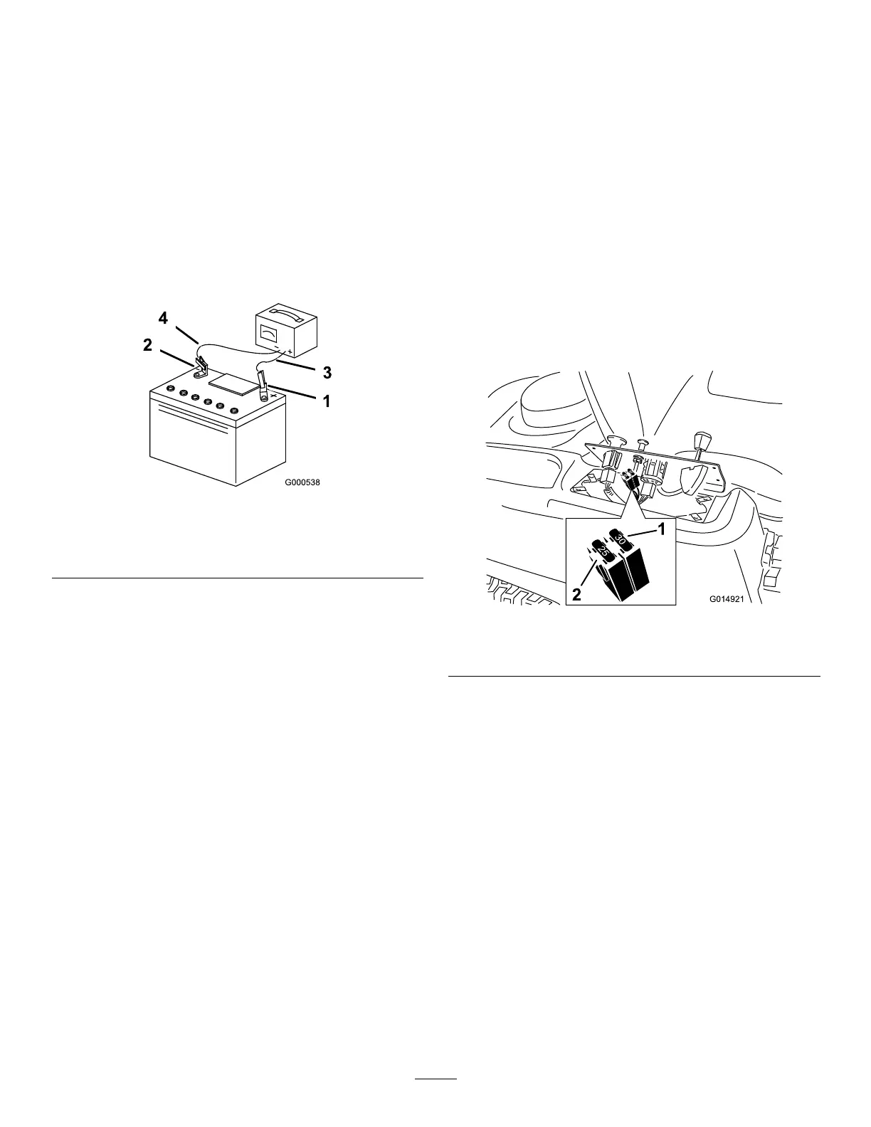
3.Whenthebatteryisfullycharged,unplug
thechargerfromtheelectricaloutlet,then
disconnectthechargerleadsfromthebattery
posts(Figure47).
g000538
Figure47
1.Positive(+)batterypost3.Red(+)chargerlead
2.Negative(–)batterypost4.Black(–)chargerlead
InstallingtheBattery
1.Positionthebatteryinthetray(Figure46).
2.Usingthefastenerspreviouslyremoved,install
thepositive(red)batterycabletothepositive
(+)batteryterminal.
3.Usingthefastenerspreviouslyremoved,install
thenegativebatterycabletothenegative(-)
batteryterminal.
4.Slidetheredterminalbootontothepositive
(red)batterypost.
5.Securethebatterywiththehold-down(Figure
46).
6.Lowertheseat.
ServicingtheFuses
Theelectricalsystemisprotectedbyfuses.Itrequires
nomaintenance;however,ifafuseblows,checkthe
component/circuitforamalfunctionorshort.
Fusetype:
•Main—F1-30A,blade-type
•ChargeCircuit—F2-25A,blade-type
1.Removethescrewssecuringthecontrolpanel
tothemachine.
Note:Retainallfasteners.
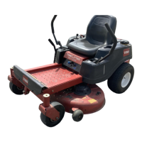
2.Liftthecontrolpaneuptoaccessthemainwire
harnessandfuseblock(Figure48).
3.T oreplaceafuse,pulloutonthefusetoremove
it(Figure48).
g014921
Figure48
1.Main—30A
2.Chargecircuit—25A
4.Returnthecontrolpaneltoitsoriginalposition.
Note:Usethescrewsremovedpreviouslyto
securethepaneltothemachine.
43