g005652
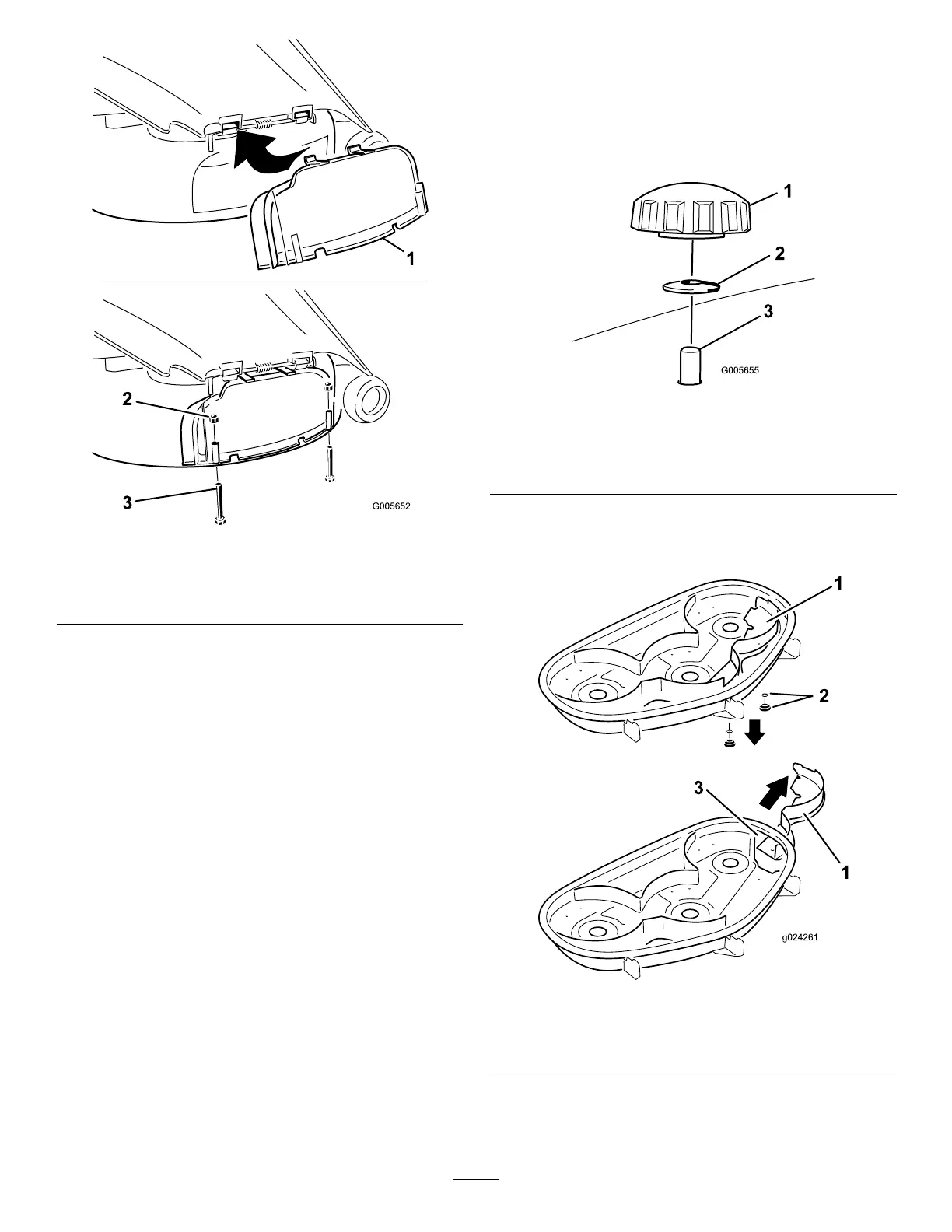
Figure25
1.Dischargecover
3.Bolt(1/4x2-1/2inches)
2.Capnut(1/4inch)
6.Securethedischargecovertothelowerlipof
themowerwith2bolts(1/4x2-1/2inches)and
2capnuts(1/4inch)asshowninFigure25.
Note:Donotovertightenthenuts;thiscould
distortthecoverandcausebladecontact.
ConvertingtoSide
Discharge
ForModelswith127cm(50-inch)
MowerDecks
Themowerdeckandmowerbladesshippedwiththis
machineweredesignedforoptimummulchingand
sidedischargeperformance.
RemovingtheRightBafeforSide
Discharge
1.Parkthemachineonalevelsurfaceand
disengagetheblade-controlswitch.
2.Movethemotion-controlleversoutwardtothe
PARKposition,shutofftheengine,removethe
key,andwaitforallmovingpartstostopbefore
leavingtheoperatingposition.
3.Removetherightmowerblade;referto
RemovingtheBlades(page47).
4.Removethe2knobsandcurvedwashersthat
securetherightbafetothemower(Figure26).
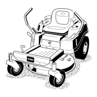
g005655
Figure26
1.Knob
3.Bafestudcomingthrough
themower
2.Curvedwasher
5.Removetherightbafeandlowerthegrass
deectoroverthedischargeopening(Figure26
andFigure27).
g024261
Figure27
1.Rightbafe
3.Dischargeopening
2.Curvedwasherandknob
6.Installthefastenersintotheholesinthetopof
themowertopreventyingdebris.
28