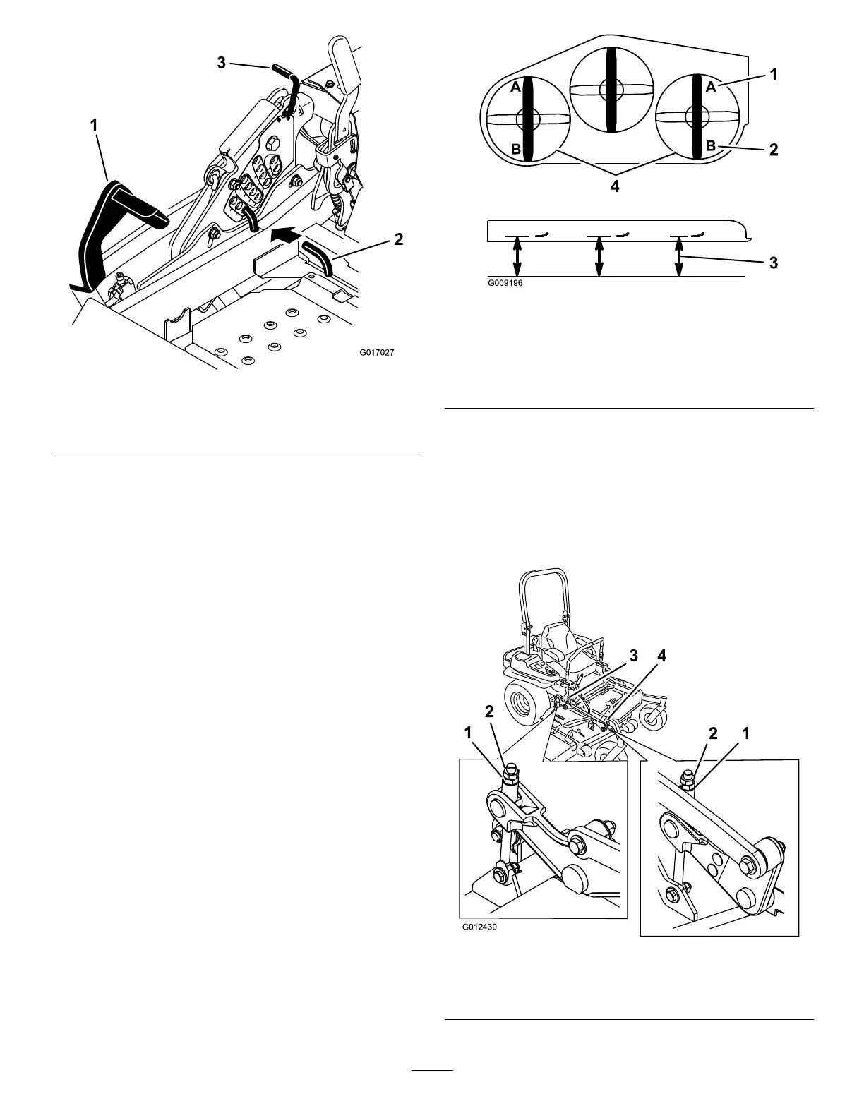
Figure91
1.Deck-liftpedal
3.Transportlock
2.Height-of-cutpin
6.Inserttheheight-adjustmentpinintothe7.6cm(3
inch)height-of-cutlocation.
7.Releasethetransportlockandallowthedecktolower
tothecuttingheight.
8.Raisethedischargechute.
9.Onbothsidesofthedeck,measurefromthelevel
surfacetothefronttipoftheblade(PostionA)as
showninFigure92.
Note:Themeasurementshouldread7.6mm(3
inches)
Figure92
1.7.6cm(3inches)at
positionAiscorrect.
3.Measureherefromthe
bladetiptothehard
surface.
2.8.3cm(3-1/4inches)at
positionBiscorrect.
4.MeasureatpositionAand
Bonbothsides.
10.Ifneeded,loosentheangedlocknutonthesideofthe
yokeandthejamnutontop.
11.Fine-tunetheadjusterscrewbyturningittoget7.6
mm(3inch)height(Figure93).
Note:Toincreasetheheight,turntheadjuster
screwclockwise;todecreasetheheight,turnit
counterclockwise.
Figure93
1.Flangedlocknut3.Jamnut
2.Adjusterscrew4.Yoke
61