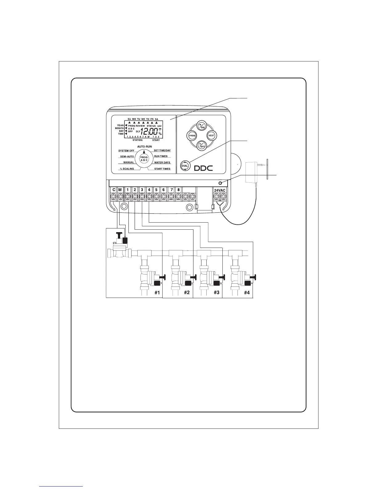
INSTALLATION INSTRUCTIONS:
Remove the lower cover of the DDC controller. Place the unit on the wall using the
top screw slot. Level the controller, then insert screws into the two lower screws
holes under the terminal block. Connect the solenoid wires to the terminal block.
Connect one wire from the solenoid to its respective station number on the
terminal block and the other wire to the C-common terminal. Finally, connect the
transformer wires to the 24 VAC terminal.
9 VDC battery. The 9 volt battery compartment is located between the sensor
terminal and the 24VAC terminal. The 9 volt battery powers the LCD display in the
absence of AC power and allows “Arm Chair Programming”. Program information
is retained during power outages by an on-board lithium battery.
Note: Only after all the wiring is completed and checked should the
transformer be plugged into AC power.
-3-
MULTILINGUAL
LCD INLAY -
To place or replace
look at instructions
inside the plastic bag.
DIGITAL DIAL
advancement button
RESET
SENSOR
9 volt
Battery
RESET
BUTTON
COMMON TO ALL VALVES
MASTER
VALVE
Install in a
protected area.
TRANSFORMER
Quick Ref.
Card