4
InstallingtheWireHarness
fortheSwitches
Partsneededforthisprocedure:
1
Flange-headbolt(1/4x3/4inch)
1
Flashermodule(CE)
1
Flangelocknut(1/4inch)
2
Cabletie
1Hornswitch
1
Jamnut(5/8inch)
1
Knurlednut(5/8inch)
1Button
1
Switch—rocker(on-off-on)
1
Switch—rocker(illuminated)
1Turn-signalswitch
1Hoseclamp
RoutingtheWireHarnesstothe
DashPanel
g208167
Figure17
1.108cm(42-1/2
inches)wireharness
branch—hornswitch,TO
HEADLIGHTSWITCHPIN1,
turnsignal,hazardswitch,
CEashermodule,andTO
MAINHARNESS
2.Forward
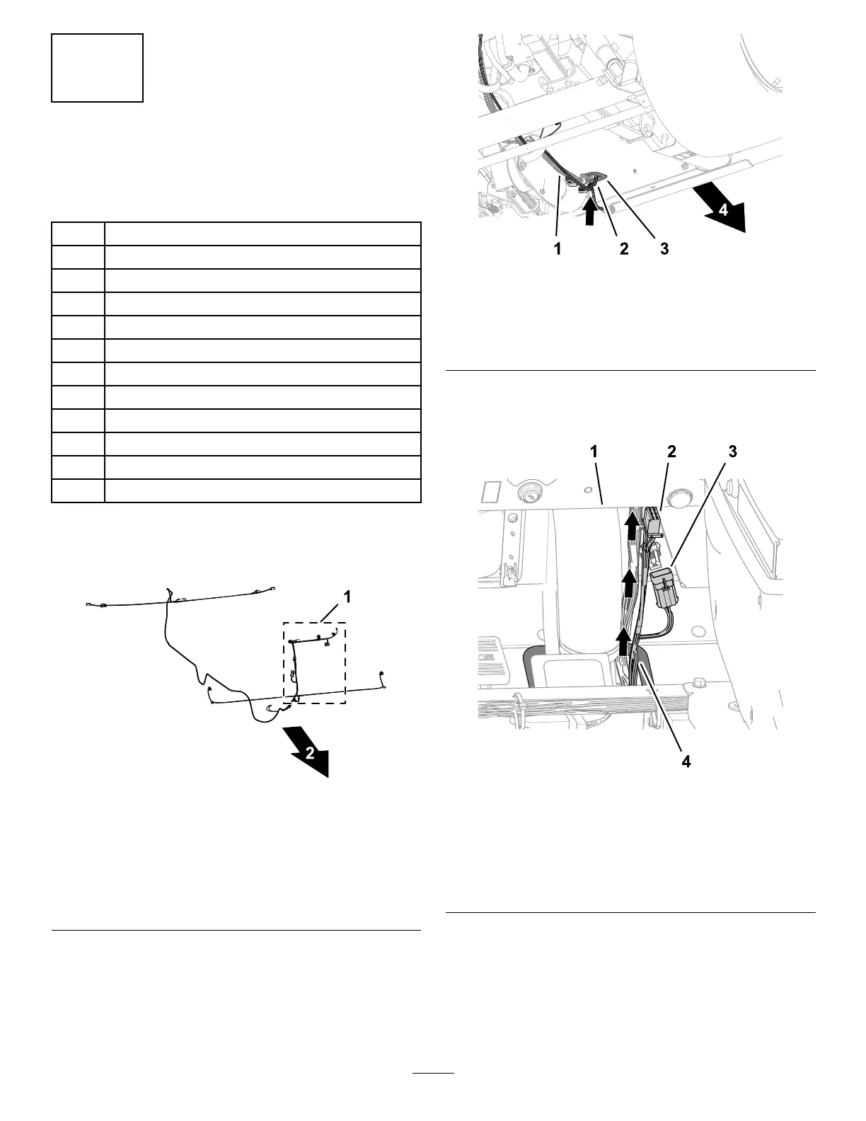
1.Routethe108cm(42-1/2inches)branchofthe
kitwireharnessupalongthefrontwireharness
ofthemachineandthroughthegrommetinthe
oorplate(Figure18).
g208202
Figure18
1.Frontwireharness
(machine)
3.Grommet(oorplate)
2.108cm(42-1/2inches)
wireharnessbranch
4.Frontofthemachine
2.Continueroutingthebranchofthekitwire
harnessupandunderthedashpanelofthe
machine(Figure19).
g208203
Figure19
1.Dashpanel3.6-pinconnector—kit
wireharness(TOMAIN
HARNESS)
2.6-socketconnector—kit
wireharness(CEasher
module)
4.108cm(42-1/2inches)
wireharnessbranch
3.Frominsidethestoragecompartment,inserta
ange-headbolt(1/4x3/4inch)thoughthehole
intheinboardwallofthecompartment(Figure
20).
9

 Loading...