Communication Cable Installation
Please note the following communication cable installation requirements and suggestions:
• The satellite is designed for use with shielded, twisted-pair, communication cable. Consult with your local Toro
distributor for the cable type and wire size best suited for your installation.
• MorethanonecableruncanbeconnectedtotheSPU.
• Asatellitecommunicationcablecanemanatefromanothersatelliteconnection.
• Ifadditionalcommunicationcablerunsareinstalledforfuturesystemexpansion,eachcablewirepairmustbeterminated
with a 600 ohm resistor.
• Ifthecommunicationcableisroutedinthesametrenchasmainpowerwires,aminimumof12”(30.5cm)separationis
recommended to prevent voltage induction on the communication cable. Check local codes for actual requirements.
• Refertotheinstallationinstructionsprovidedwiththecentralcontrolsystemforcommunicationcabletesting
procedures.
• If in-ground cable splices or repairs are required, the connection must be properly insulated with a waterproof splicing
device. Using an appropriate splicing kit, such as Scotchcast 82-A1 (or equivalent), is recommended. Placing the cable
splice in a small valve box for protection and accessibility is also recognized as good installation practice.
Procedure
1. Starting at the SPU, route the
communication (comm) cable to
each satellite leaving enough cable at
each location to enable connection.
See Figure 10.
*Note: If additional communication
cable is installed for future
system expansion, connect a
600 ohm resistor across the wire pair
at the end of the cable as shown in
Figure 11.
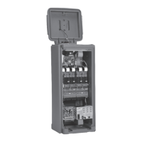
2. At the satellite, cut the cable and pull
both ends into the satellite through
the 3/4” (16mm) sweep conduit.
3. From the cable ends, carefully
remove the outer jacket and inner
insulation to expose the comm wires
and drain wire. If installing cable in
a satellite without surge protection,
expose 5” (12.7cm) of wire; with
surge protection, expose 2” (5.1cm)
of wire. Remove 3/8” (10mm)
insulation from the ends of each
comm wire.
4. Clamp the cable to the chassis
assembly and secure the comm and
drain wires as shown in the optional
or standard configurations as shown
in Figure 12.
Note: Remove the modem wire
connector(s) until the comm cable has
been tested. Refer to the installation
instructions provided with the central
controller for testing procedures.
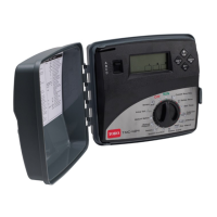
Refer to the Network VP Satellite
User’s Guide for programming and
operation procedures.
Figure 12
Connection
To Modem
Connection
To Modem
Drain
Wire
Drain
Wires
Drain
Wire
Comm
Cable Out
Comm
Cable Out
Comm
Cable In
Comm
Cable In
Gray Comm
Wires
Gray Comm
Wires
Yellow Comm
Wires
Yellow Comm
Wires
Figure 10
Satellite
Optional
Standard
SPU
Figure 11
600 Ohm
Resistor
See *Note