Field Wire Installation
CAUTION: The Network VP satellite is
capable of operating up to 32 stations
and the pump/master valve circuit
concurrently. To prevent possible
controller damage, total current load for all
field outputs operating concurrently must
not to exceed 3.2A. If more than one valve
per station is required, calculate the total
in-rush current load which would be
imposed in the maximum operating
conditions and use this value as a guide
during installation and operation of the
controller.
Procedure
1. Attach the control and common wires to
each valve and/or valve-in-head solenoid
leads using an approved waterproof splicing
method. Route the wires into the controller
cabinet through the 3” (76mm) conduit.
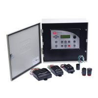
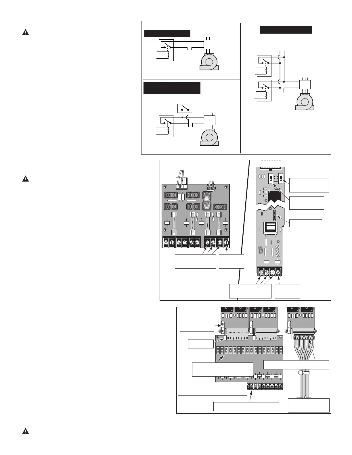
2. If automatic pump start is required, refer to
the applicable wiring diagram in Figure 7 and install
accordingly.
CAUTION: Do not connect the pump starter
directly to the controller’s pump start circuit.
Damage to the controller will result.
Note: The pump circuit can also be utilized to control a
master valve if required.
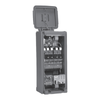
3. Secure the field common wire(s) and pump start relay
(or master valve) wire to the appropriate terminals
on the Pump/Com module OR (optional) Pump/Com
Surge Protection module. See Figure 8.
4. Momentarily touch each valve control wire to the
Hot Post to activate and identify the corresponding
valve(s).
5. Secure the valve control wires to the station terminals
in the preferred order of operating sequence. Station
terminals are numbered left to right, 1–32 (front) and
33–64 (back). See Figure 9.
Note: A 3-position switch is provided on the Pump/Com
module for additional control of the pump relay circuit.
In addition, the optional station terminal modules
with optional control switches have one switch for
each station output. See Figures 8 and 9. The three switch
positions control the circuits as follows:
On – Manually activates the circuit. The pump or station will
remain on until the switch is moved to the Auto or Off position.
Off – Switches the circuit off, preventing pump or station
operation from the satellite.
Auto – The circuit is automatically activated by the controller
during automatic or manual watering operation.
As an added lightning protection measure, the field common
circuit is normally open when the controller is inactive.
Therefore, to use the field output control switches for manual
operation, the common circuit must be engaged first.
Press the Field Common Engage push button switch to
activate the circuit. The Field Common Indicator Lamp will
turn on when the circuit is active. The common circuit will
automatically disconnect upon completion of an automatic or
manually activated watering operation initiated through the
timing mechanism. The circuit can also be disconnected by
momentarily switching the power supply off.
CAUTION: To prevent damage to the 3.2A field output circuit fuse,
do not exceed 3.2A load when manually activating multiple field outputs.
1
PUMPCOMMON
PUMPCOMMON
ON
AUTO
OFF
Figure 8
Pump/Com Module
Optional Pump/Com &
Communication Surge
Protection Module
Field Common
Terminals
Field Common
Terminals
Pump
Terminal
Pump
Terminal
Pump Circuit
Switch
Field Common
Engage Switch
Multiple Controllers
Single Controller
Pressure Switch With
Controller Override
Starter
Power
Source
Starter
Power
Source
Starter
Power
Source
Pump Power
Source
Pressure Switch
Pump Power
Source
Pump Power
Source
Relay
24 VAC
.75A Max.
Relay
24 VAC
.75A Max.
(Typical)
Relay
24 VAC
.75A Max.
Pump
Pump
Pump
Pump
Pump
Pump
Pump
Com
Com
Com
Com
Magnetic
Pump
Starter
Magnetic
Pump
Starter
Mag.
Pump
Starter
To Other
Controllers
Figure 7
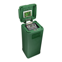
Station Output Control
Switches (Optional)
Hot Post
Standard
Terminal Block
Surge Protection Terminal
Block (Optional)
Figure 9
3-Amp Fuse
1-Amp Fuse
Station Output Terminals
Station Output Terminals