Input Power Installation
CAUTION: When installing multiple controllers, polarity of the Line and Neutral connections must be properly
maintained throughout the irrigation system. Reversed polarity may cause damaging potentials to exist at one or
more controller locations.
Procedure
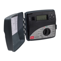
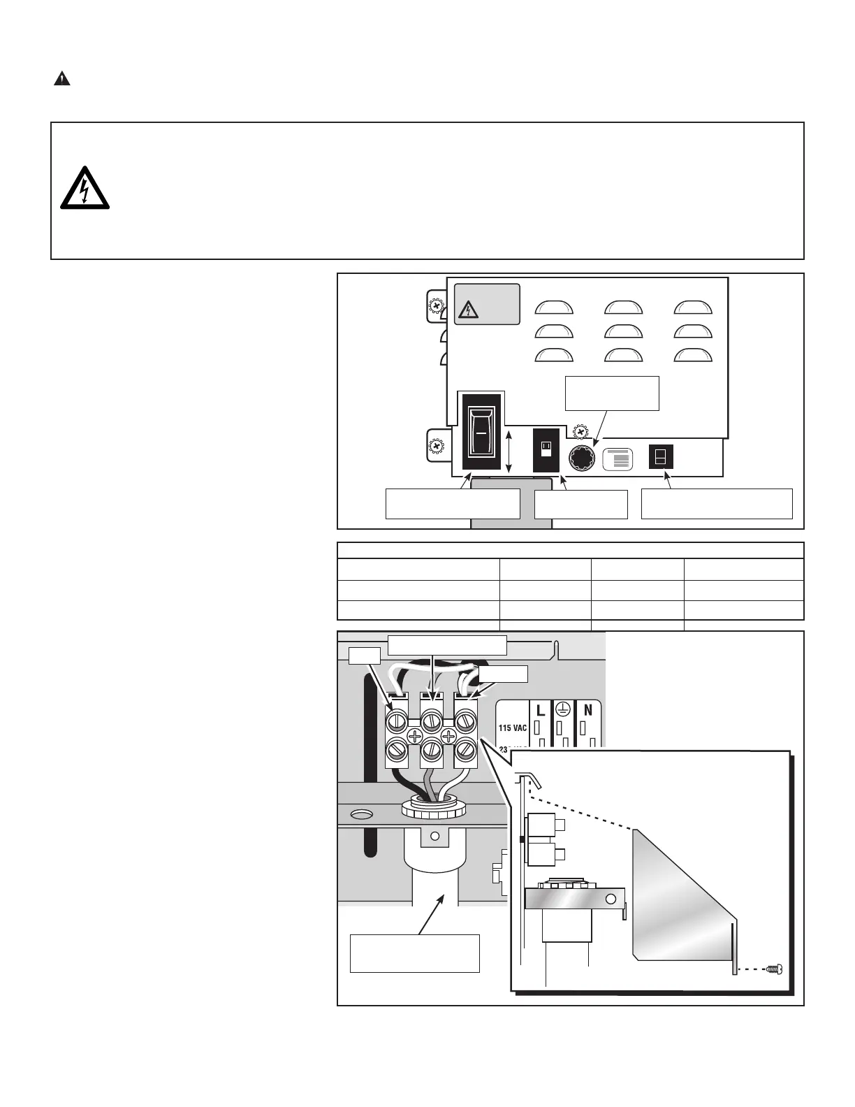
1. Place the controller’s main power switch in
the Off position. See Figure 5.
2. Position the input voltage select switch to
the 115V or 230V position as required.
3. Loosen the phillips screw on the back of
the power supply assembly and remove the
cover. See Figure 6.
Note: The power and equipment ground wires
are connected to a terminal block located
on the back of the power supply assembly.
The power wire access hole provided will
accommodate a 3/4” (19mm) conduit fitting.
If conduit is required, install a section of
flexible 3/4” (19mm) electrical conduit from the
foundation conduit to this access hole.
4. Route the appropriate size 3-conductor cable
(10 AWG [2.5mm
2
] maximum) from the
power source location to the power supply
terminal block.
5. Reference Table 1 for the appropriate type
of power connection. Secure the wires to
the terminal block as indicated in Figure 6.
6. Reinstall the power supply assembly cover.
7. Apply power to the controller.
Note: The Network VP satellite incorporates
a 24 VAC Hot Post feature on each station
output module which enables control valves to
be identified through momentary activation. To
utilize the Hot Post feature, the satellite power
supply must be switched on.
If you do not wish to use the Hot Post feature,
leave the controller’s main power switch off
until the installation has been completed.
115V
WARNING
HIGH
VOLTAGE
4
M
A
P
On
Off
Figure 5
WARNING
AC POWER WIRING MUST BE INSTALLED AND CONNECTED BY QUALIFIED PERSONNEL ONLY.
ALL ELECTRICAL COMPONENTS AND INSTALLATION PROCEDURES MUST COMPLY WITH ALL APPLICABLE
LOCAL AND NATIONAL ELECTRICAL CODES. SOME CODES MAY REQUIRE A MEANS OF DISCONNECTION
FROM THE AC POWER SOURCE, INSTALLED IN THE FIXED WIRING, HAVING A CONTACT SEPARATION OF AT
LEAST 0.120” (3MM) IN THE LINE AND NEUTRAL POLES.
ENSURE THE AC POWER SOURCE IS OFF PRIOR TO CONNECTING TO THE CONTROLLER.
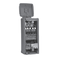
Main Power Switch/
1.5A Circuit Breaker
Input Voltage
Select Switch
3.2A Fuse –
Station Output
4.0A Circuit Breaker –
Control Functions
Line
Hot (Black)
Hot (Brown)
Neutral
Neutral (White)
Neutral (Blue)
Equip. Grnd.
Green
Green/Yellow
AC Service Type
115 VAC (Domestic)
230 VAC (International)
Table 1
Figure 6
3/4” (19mm) Flexible
Conduit (Optional)
Line
Equipment Ground
Neutral