Earth Ground Installation
IMPORTANT! The satellite surge protection components cannot properly function unless an efficient pathway to earth
ground is provided. The ground path must be as direct as possible, without sharp bends and must not exceed 30 ohms
resistance (when measured with an earth ground resistance test device). A resistance reading of 0–10 ohms is considered
excellent, 11–20 ohms is acceptable and 21–30 is considered marginal. All electrical components throughout the irrigation
system should be grounded in a manner which provides the same ground potential.
The following instructions depict one of
several acceptable earth grounding methods.
Due to variables in soil composition and
terrain, the method shown may not be suitable
for your installation site. Contact your local
Toro distributor for assistance and availability
of the required earth ground resistance test
instrument. Recommended ground testers
are: AEMC Instruments, model 3710 clamp-on
tester, or Biddle Megger, model 250260
(or equivalent).
Procedure
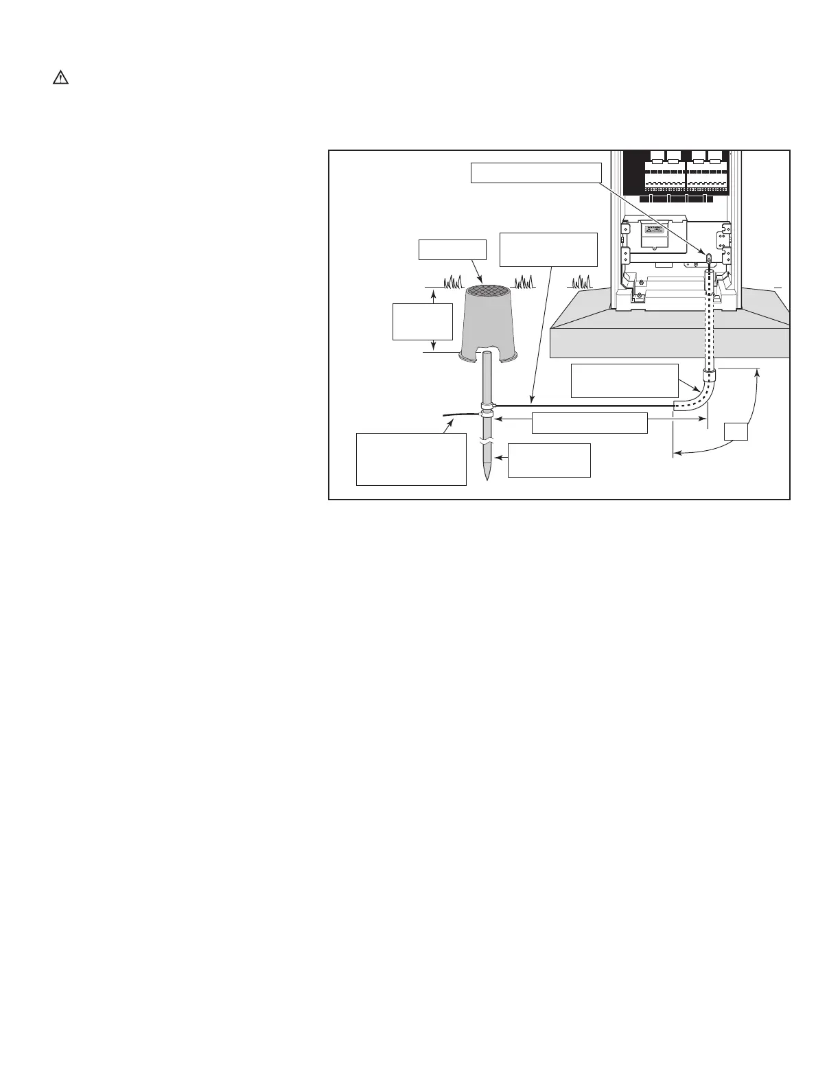
1. Drive a 5/8” by 8’ (17 mm x 2.4 m)
copper-clad steel rod into well moistened
soil not less than 8’ (2.5 m) or more than
12’ (3.7 m) from the satellite. The top of
the ground rod should be 12” (30.5 cm)
below grade level. See Figure 4.
2. Using a 5/8” (17 mm) clamp or “Cad weld”
fastener, attach a 6 AWG (10 mm
2
) solid
copper wire near the top of the ground
rod. Avoiding wire bends of less than
8” (20.3 cm) radius and more than 90°,
route the wire through conduit into the controller cabinet. Secure the wire to the large copper ground lug. See Figure 4.
Note: Make sure the soil surrounding the ground rod(s) remains well moistened at all times. The addition of some form of
irrigation may be required if the satellite is installed in a non-irrigated location.
3. Measure the ground resistance per the instructions provided with the ground test instrument. A reading of 0 ohms is
optimum, up to 10 ohms is good and 11-30 ohms is acceptable in most cases. If the resistance exceeds the acceptable
limit, additional ground rod(s) can be installed at a distance equal to twice the buried depth of the first rod; i.e., 16’
(4.9 m). Interconnect the ground rods using 6 AWG (10 mm
2
) solid copper wire and test again. If the measured ground
resistance continues to read above the acceptable limit, contact your local Toro distributor for further assistance and
recommendations.
Note: Installing a round valve box over the ground rod enables the ground rod to be easily located as well as providing
access to the ground wire connection(s).
Figure 4
Chassis Ground Lug
Valve Box
6 AWG (10mm
2
)
Ground Wire
12”
(30.5cm)
8” (20.3cm)
Radius Minimum
Ground Wire To
Additional Rod(s)
(Optional)
Copper-Clad
Ground Rod
8’–12’ (2.4m–3.7m)
90
o