g004200
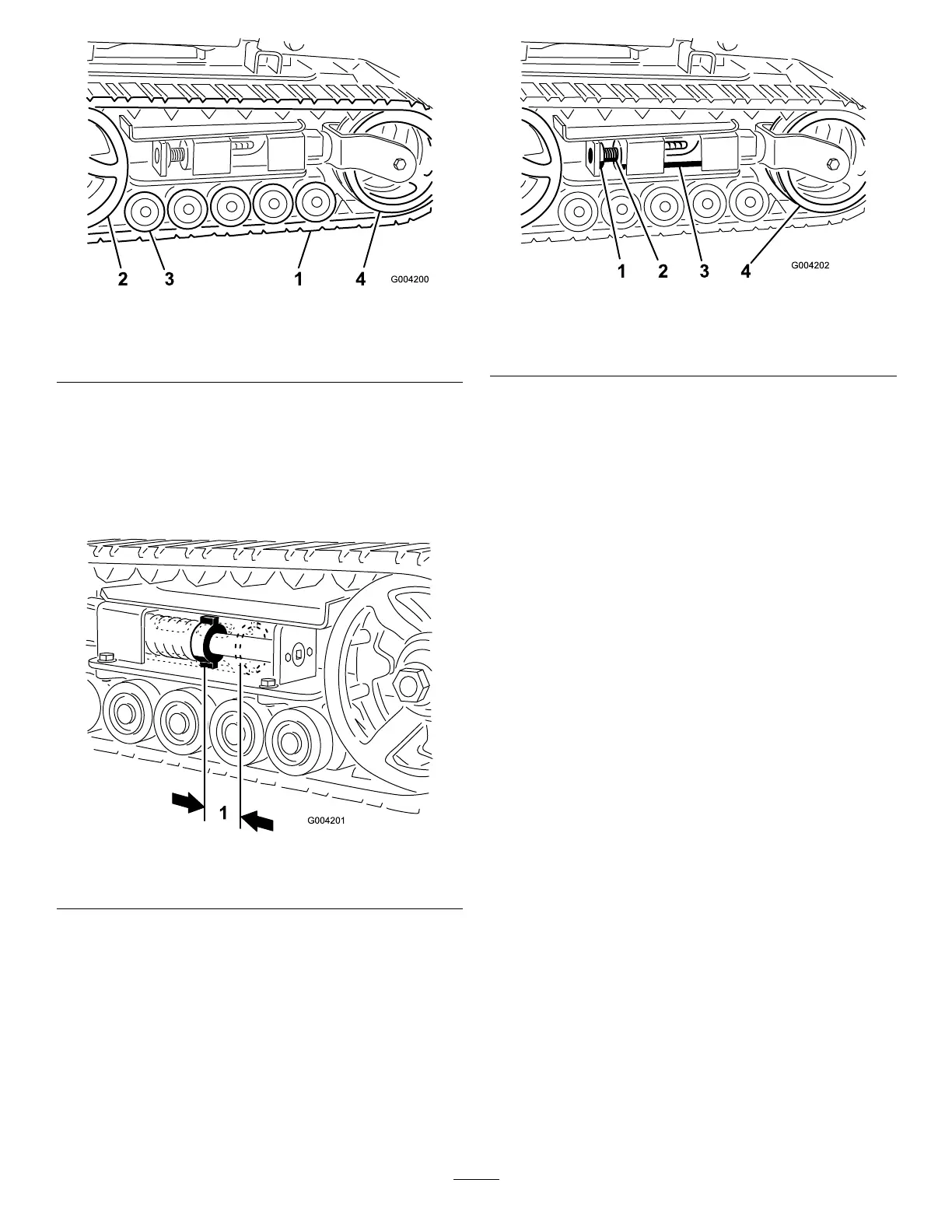
Figure45
1.Track3.Roadwheels
2.Drivesprocket4.Tensionwheel
AdjustingtheTrackTension
Thereshouldbe7cm(2-3/4inches)betweenthe
tensionnutandthebackofthetensiontube(Figure
46).Ifnot,adjustthetracktensionusingthefollowing
procedure:
g004201
Figure46
1.7cm(2-3/4inches)
1.Parkthemachineonalevelsurface,engagethe
parkingbrake,andlowertheloaderarms.
2.Shutofftheengineandremovethekey.
3.Lift/supportthesideoftheunittobeworkedon
sothatthetrackisofftheground.
4.Removethelockingboltandnut(Figure47).
g004202
Figure47
1.Lockingbolt3.Tensiontube
2.Tensioningscrew4.Tensionwheel
5.Usinga1/2-inchdriveratchet,turnthe
tensioningscrewcounterclockwiseuntilthe
distancebetweenthetensionnutandtheback
ofthetensiontube(Figure46)is7cm(2-3/4
inches).
6.Aligntheclosestnotchinthetensionscrewto
thelockingboltholeandsecurethescrewwith
thelockingboltandnut(Figure47).
7.Lowerthetractionunittotheground.
ReplacingtheTracks
ReplacingNarrow-WidthTracks
Whenthetracksarebadlyworn,replacethem.
Note:Youhavenarrow-widthtracksifthefront
tensionwheelsaremountedinsideaforkontheend
ofthetensiontube(Figure48).
1.Parkthemachineonalevelsurface,engagethe
parkingbrake,andlowertheloaderarms.
2.Shutofftheengineandremovethekey.
3.Lift/supportthesideoftheunittobeworkedon
sothatthetrackis8to10cm(3to4inches)
offtheground.
4.Removethelockingboltandnut(Figure47).
5.Usinga1/2-inchdriveratchet,releasethe
drivetensionbyturningthetensioningscrew
clockwise(Figure47andFigure48).
35