ProductOverview
g005550
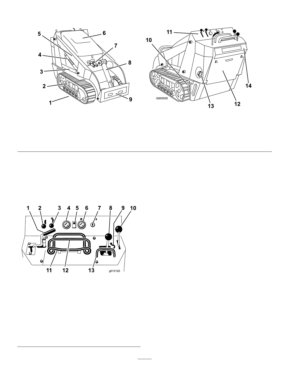
Figure3
1.Track5.Loaderarms9.Mountplate13.Fueltank
2.Track-adjustmentchamber6.Hood
10.Tie-down/liftloop14.Reverse-safetyplate
3.Liftcylinder
7.Auxiliaryhydrauliccouplers
11.Controlpanel
4.Cylinderlock
8.Tiltcylinder12.Rear-accesscover
Controls
Becomefamiliarwithallthecontrols(Figure4)before
youstarttheengineandoperatethetractionunit.
ControlPanel
g013120
Figure4
1.Auxiliaryhydraulicslever
8.Loader-arm/attachment-tilt
lever
2.Throttlelever9.Loader-valvelock
3.Chokelever
10.Parking-brakelever
4.Fuelgauge11.Tractioncontrol
5.Hydraulic-uid-temperature
light
12.Referencebar
6.Hourmeter/tachometer13.Loader-control-reference
bar
7.Keyswitch
KeySwitch
Thekeyswitch,usedtostartandshutofftheengine,
has3positions:OFF,RUN,andSTART.Referto
StartingtheEngine(page15).
ThrottleLever
Movethecontrolforwardtoincreasetheenginespeed
andrearwardtodecreasespeed.
ChokeLever
Beforestartingacoldengine,movethechokelever
forward.Aftertheenginestarts,regulatethechoke
tokeeptheenginerunningsmoothly.Assoonas
possible,movethechokeleverallthewayrearward.
Note:Awarmenginerequireslittleornochoking.
ReferenceBar
Whendrivingthetractionunit,usethereferencebar
asahandleandaleveragepointforcontrollingthe
tractioncontrolandtheauxiliary-hydraulicslever.T o
ensuresmooth,controlledoperation,donottake
bothhandsoffthereferencebarwhileoperatingthe
machine.
9