INSTALLATION PROCEDURE FOR OPTIONAL EQUIPMENT EO15-33005
2. Wireless LAN Board: B-EP700-WLAN-QM-R
2- 1
2. Wireless LAN Board: B-EP700-WLAN-QM-R
Thank you for purchasing TOSHIBA wireless LAN kit, B-EP700-WLAN-QM-R.
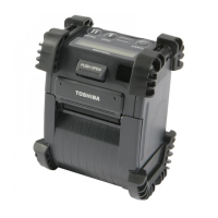
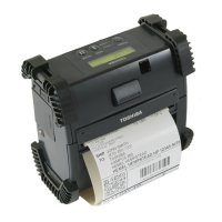
The B-EP700-WLAN-QM-R is an optional wireless LAN interface board for the B-EP2D/EP4D Series.
The pictures used in this document are those of the B-EP4D, but the installation procedure is common with
the B-EP2D unless otherwise noted.
• Packing List
The following parts are supplied with the kit. Make sure you have all items shown below.
Wireless LAN Board (1 pc.)
FPC cable (2 pcs.)
Installation Manual (1 copy)
• Installation Procedure
1. Turn off the printer.
2. Slide the battery lever in the direction of the arrow, and remove the battery pack from the printer.
3. Remove the four tapping screws (T-3x10) from the bottom cover.
1. Follow all manual instructions. Failure to do so could create safety hazards such as fire or
electrocution.
• Manual instructions must be followed when installing option kits or adding cables to avoid
system failures and to insure proper performance and operation.
• Failure to follow manual instructions or any unauthorized modifications, substitution or change to
this product will void the limited product warranty.
2. Turn the power off and remove the battery before installing the wireless LAN module.
3. Be careful not to
inch
our fin
ers or hands with the covers.
WARNING!
Battery Lever
Battery Pack
T-3x10 Tapping Screw
T-3x10 Tapping Screw

 Loading...