10
Introduction
Components
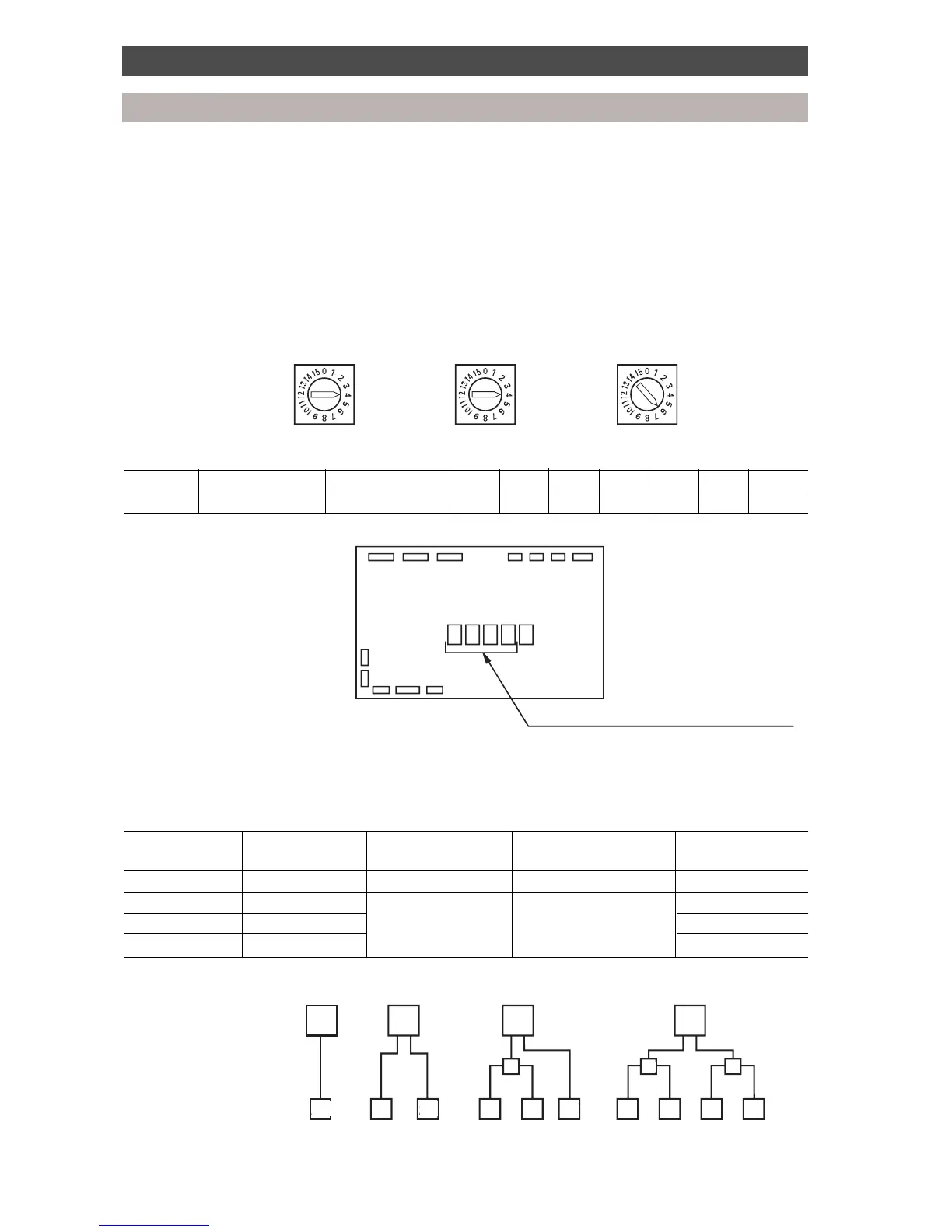
Setting of indoor unit capacity codes
• The setting of the indoor unit capacities is important. Set the correct indoor unit code numbers
according to the indoor unit capacity. The capacities are set by the rotary switches on the printed
circuit board switch A (unit A), switch B (unit B), switch C (unit C) and switch D (unit D).
• During manufacture, the indoor capacity selection switches are set at ‘0’.
• Record the indoor capacity codes, indoor unit model names and locations in the installation manual,
and on the wiring diagram on the electrical panel cover.
Example: Room A Room B Room C
Capacity 16 Capacity 16 Capacity 26
Indoor unit Capacity No connection 10 13 16 20 26 36 46
Code number 0 2 3 4 5 6 8 10
(Example: Model RAV-364UH-PE, capacity = 36)
Multi Controller PCB
MCC-1210
Capacity select switches
• Multiple indoor units may be connected to each outdoor unit, providing the total indoor code does not
exceed the limits shown below.
Combination of Multi Controllers and indoor units
Number of Maximum No. of Indoor unit diversity Maximum system code Maximum code per
Multi Controllers indoor units Multi Controller
1 4 135% 27 27
2 8 160% 32 27
3 12 27 (13*)
416 13
Example of systems with maximum possible code:
OD OD
DIF DIF DIF
27 13
OD
27 2713 13 13 13 13
OD
27
Outdoor unit
Interface kit
Multi Controller [code]
(Max. system code)
OD OD
OD
OD
DIF
DIFDIF
27 2666
6
8888
20
(27) (32)(32)
(32)
 Loading...