20
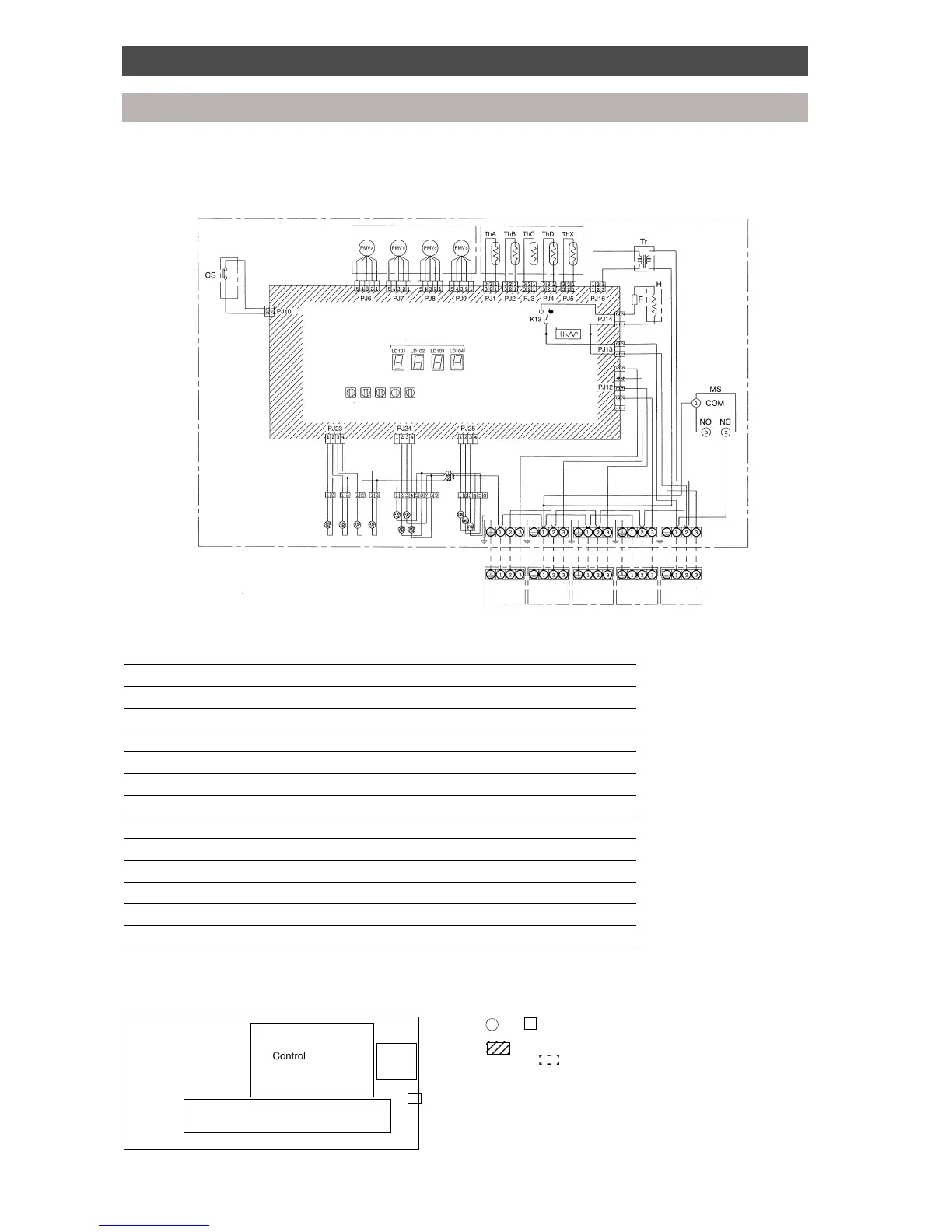
Wiring diagram
Multi Controllers
3-pipe Multi Controller (RBM-Y1034F-PE, RBM-Y1044F-PE)
Symbol Part Name
PMVA, B, C, D Pulse modulating valve
Th A, B, C, D, X Temperature sensor
Tr Power transformer
CS Float switch
H Heater
MS Reset switch
F Fuse (T1A)
SVD (A), (B), (C), (D) Electrically operated valve for discharge gas side
SVD (A), (B), (C), (D) Electrically operated valve for suction gas side
SVDD Electrically operated valve for increasing pressure
SVSS Electrically operated valve for decreasing pressure
SVH Electrically operated valve for superheat control
LD 101, 102, 103, 104 Fault indicator LED
Parts layout
• The dashed lines indicate wiring on site.
• and indicate terminal blocks, and numbers within them are
terminal numbers.
• indicates a printed circuit board.
• The frame indicates the product body.
• RBM-Y1034F-PE does not have PMVD, SVD(D), SVS(D), ThD or the
connection block for indoor unit D.
The capacity rank code setting for unit D is to be set to “0”.
 Loading...