9
Introduction
Outline of control system
The refrigerant and electrical systems of the Super Multi air conditioner are controlled by the Multi
Controller and the outdoor unit microprocessors.
All RAV heat pump, R-407C, 4/5 series indoor units are compatible with the Super Multi system, i.e. 1~5 HP.
For system operation, initially the microprocessor in each indoor unit calculates the difference between the
current room temperature (TA) and the requested temperature which has been set on the remote
controller. A demand signal is determined and transmitted to the Multi Controller microprocessor in the
form of operation commands (i.e. ON/OFF, cooling or heating operation mode, operation demand frequency).
The Multi Controller microprocessor receives operation commands from all indoor units connected,
calculates the accumulative operation command and transmits this information to the outdoor unit interface
microprocessor.
The interface microprocessor calculates the capacity required for heating or cooling and determines the
operation mode of the outdoor unit and the actual frequency of the compressor.
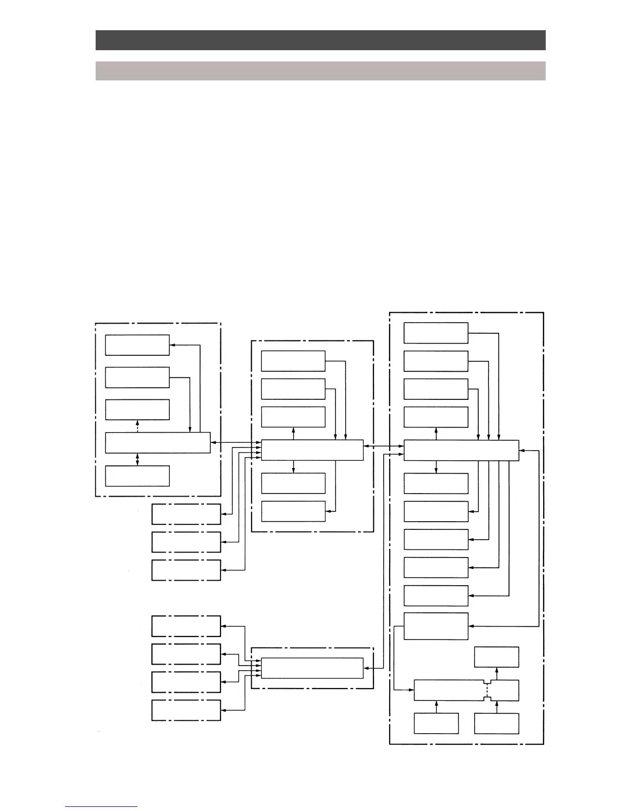
Control system diagram
Indoor unit 1-A
Multi Controller 1
Outdoor unit
Fan
Fan
Temp. sensor (TA)
Temp. sensorTemp. sensor
Drain pump
Indoor unit microprocessor
Interface microprocessorMulti Controller microprocessor
Multi Controller microprocessor
Multi Controller 2
Remote controller
Capacity rank
setting switch
Pulse modulating
valve
2-way valve
Display LED
Protection unit
Comp. sensor
Pulse modulating
valve
D.O.L. compressor
Display LED
2-way valve
4-way valve
Communication
PCB
Inverter
compressor
IPDU
Inverter
Protection
unit
Power
supply
1 - B
1 - C
1 - D
2 - A
2 - B
2 - C
2 - D
 Loading...