27
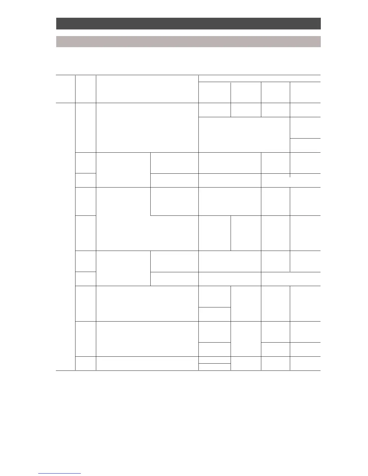
Diagnostic procedure
Outdoor unit
1. Communication serial signals and the system operating status are displayed by changing display
switch SW2.
Display Display Indication 7-segment LED display
switch switch LD 71 LD 72 LD73 LD74
SW1 SW2
position position
0 0 Sending/receiving status of Between Between Between Non-inverter
interface control board serial M/C (1) M/C (2) inverter compressor
signal Sending Not sending Abnormal [E]
only [S] or receiving
[ ]
Receiving Sending and Normal [0]
only [J] receiving [0]
1 Operating instruction Operating Heating [H], Simultaneous ---------- ----------
from M/C (1) mode cooling/heating [HC],
Cooling [C], Stop [ ]
2 Instruction Heating frequency [00-1F] Cooling frequency [00-1F]
frequency (Refer to conversion table 2) (Refer to conversion table 2)
3 Outdoor unit Operating Heating [H], Cooling [0C], ---------- ----------
operating condition mode Simultaneous heating [Hc]
Defrost [J0], Simultaneous
cooling [hC]
4 M/C Frequency ---------- ----------
operation release
Off: [0] No: [0]
1 unit: [1] Yes: [1]
2 unit: [2]
5 Operating instruction Operating Heating [H], Simultaneous ---------- ----------
from M/C (2) mode cooling/heating [HC],
Cooling [C], Stop [-]
6 Instruction Heating frequency [00-1F] Cooling frequency [00-1F]
frequency (Refer to conversion table 2) (Refer to conversion table 2)
9 Inverter operation status Normal Operating ---------- ----------
[C] frequency
[0-F],
Abnormal (Refer to
[E] table 3)
10 Operating instruction to Normal Operating ---------- ----------
inverter from interface [C] frequency
control board [0-F],
Abnormal (Refer to ---------- ----------
[E] table 3)
11 Power supply frequency 50 Hz [5] [0] ---------- ----------
60 Hz [6]
 Loading...