29
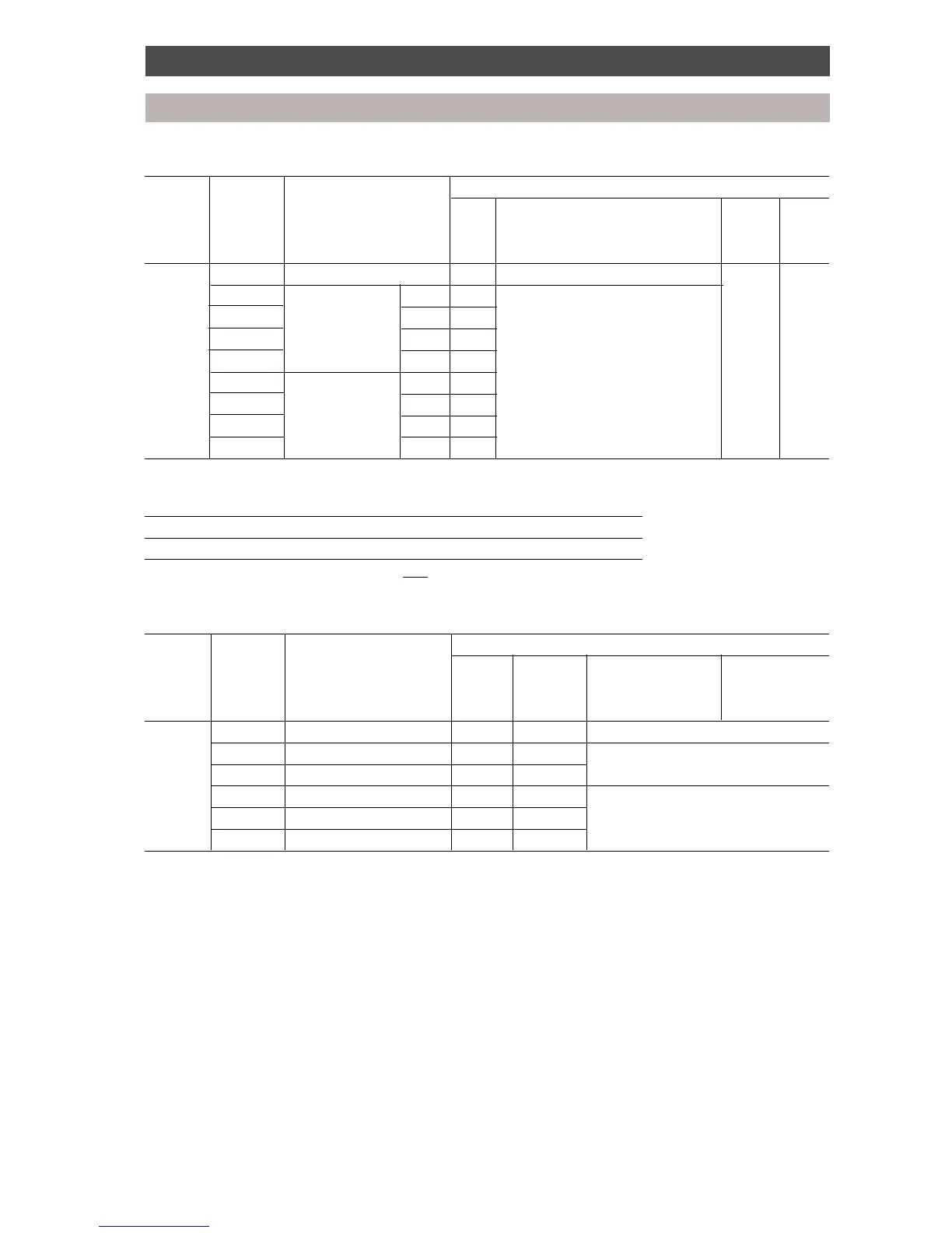
Diagnostic procedure
Outdoor unit
6. The indoor unit capacity rank setting is displayed.
Display Display Indication 7-segment LED display
switch switch LD 71 LD 72 LD 73 LD 74
SW1 SW2
position position
3 0 Outdoor unit HP [9] 8 HP [8], 10 HP [A] [H] [P]
1 Capacity rank of Unit A [A] Displays the code number of the
2 indoor unit Unit B [b] indoor unit registered to each M/C.
3 connected to Unit C [C]
4 M/C (1) Unit D [d] Refer to the table below (7) for
5 Capacity rank of Unit A [A] indoor unit model capacity rank.
6 indoor unit Unit B [b]
7 connected to Unit C [C]
8 M/C (2) Unit D [d]
7. Indoor unit code No. conversion table
Code No. 0 23456810
Capacity rank No correction 10 13 16 20 26 36 46
(Indoor unit model example: Model RAV-364UH-PE, capacity rank = 36)
8. Sensor temperature display
Display Display Indication 7-segment LED display
switch switch LD 71 LD 72 LD 73 LD 74
SW1 SW2
position position
4 0 Pressure sensor data [P] [d] Refer to table 9 conversion chart
1 ThD1 sensor data [d] [1] Refer to table 10 conversion chart
2 ThD2 sensor data [d] [2]
3 ThS sensor data [S] [1] Refer to table 11 conversion chart
4 TE sensor data [h] [E]
5 TO sensor data [h] [0]
 Loading...