31
Diagnostic procedure
Outdoor unit circuit test procedure
12. Outdoor unit circuit test procedure
• These systems have a feature which enables them to check that the wiring and piping connections
are aligned with each other. This is carried out by allowing refrigerant to flow to one indoor unit at a
time and monitoring that indoor unit’s coil sensor for a corresponding drop in temperature. Each
indoor unit is tested in turn and where two Multi Controllers are installed each Multi Controller is tested
in turn.
• This test would normally be used at the commissioning stage.
• Procedure for initialising the circuit test.
1. Turn the power off.
2. Ensure the capacity codes are set correctly, capacity switches set to ‘0’ are not tested.
3. Put the outdoor display switches SW1 and SW2 to 9 and Multi Controller(s) display switch to 6.
4. Turn the power back on.
5. Set all the remote controllers to cool mode and 29°C.
6. Press the on/off button to start all the indoor units (the outdoor LEDs show ‘1020’).
7. Press the outdoor unit switch SW3, and hold for 3 seconds.
8. The system is now in self-testing (all 8 LEDs will be flashing rapidly).
9. The system will stop at the end of the test.
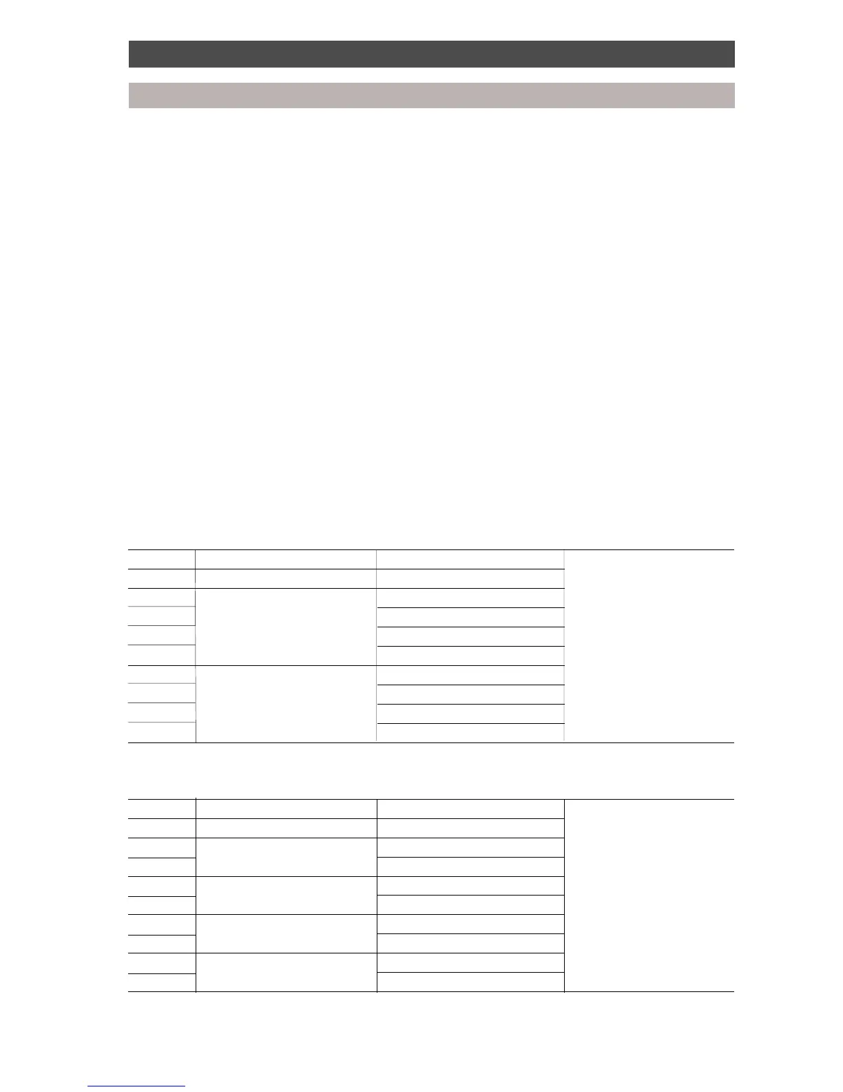
• In the event of cross wiring/piping the system will indicate which units are faulty, see table below:
Outdoor display switch SW1 and SW2 set to position 9.
One and two Multi Controllers
Display Multi Controller Fault
1020 All None
1A20 1 Unit A
1B20 Unit B Units that are indicated
1C20 Unit C failed the test
1D20 Unit D
102A 2 Unit A
102B Unit B
102C Unit C
102D Unit D
Three or more Multi Controllers
Display Multi Controller Fault
1020 All None
1A20 1 Unit A or B
1B20 Unit C or D Units that are indicated
1C20 2 Unit A or B failed the test
1D20 Unit C or D
102A 3 Unit A or B
102B Unit C or D
102C 4 Unit A or B
102D Unit C or D
 Loading...